Installation of the 7523A GX-R2 Modem Unit (SMB3315)
98-175666-D Chapter 2: Installation 2-33
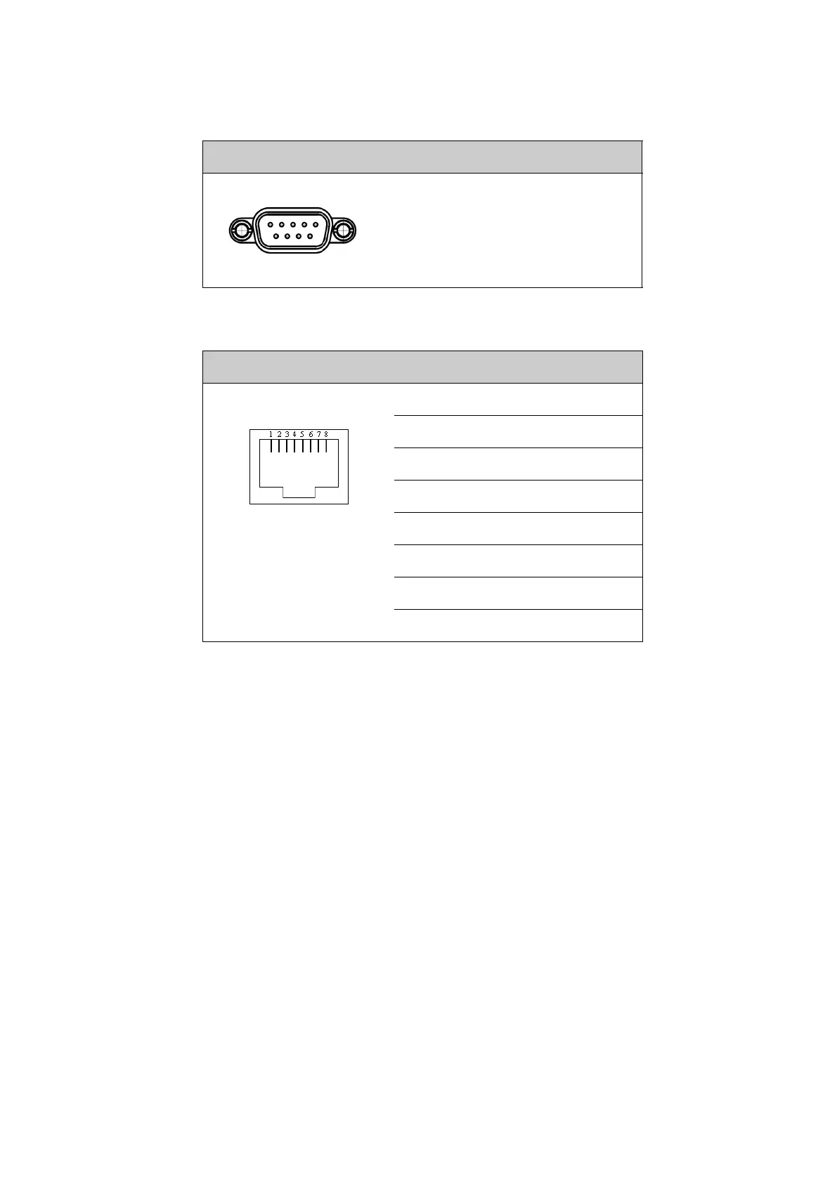
LAN connectors
The modem has several Ethernet connectors (type RJ45). Port 1 connects to the BDU
and is used for modem control. The other ports are not used. The maximum cable
length per connection is 100 m. The Ethernet cable type must be CAT5, shielded. For
outline and pin allocation see LAN connectors on page 2-30.
GMU cables for 407523A (RS-232 and RS-422)
The serial connections of the SAILOR GMU 407523A and the SAILOR XTR BDU 407516A
use standard Ethernet LAN cables (RJ-45 male to RJ-45 male) with 8 straight-through
wires. These serial cables are Customer Furnished Equipment (CFE) and must be
acquired locally.
Outline (on the modem) Pin Pin function
- Not used with 407516A BDU.
Used with 407016A ACU.
Table 2-23: RS-422 connector, male. Used with 407016A ACU
Outline (on the modem) Pin I/O Pin function
1 - NC
2 - NC
3 I RESET_CM_P
4 - Ground
5 - Ground
6 I RESET_CM_N
7 O KEYLINE_CM_P
8 O KEYLINE_CM_N
Table 2-24: RJ45 RS-422 connector (407523A), female, outline and pin
assignment, modem. Used with 407516A BDU.
1 5
6 9

 Loading...


