Installation of the BDU
98-175666-D Chapter 2: Installation 2-30
LAN connectors
The BDU has four Ethernet connectors (type RJ-45), located at the back of the unit, for
PC/laptops, routers, wireless access points. LAN port 5 is for service access at the front.
Depending on the VSAT modem, one LAN connector may be used for modem control.
The maximum cable length per connection is 100 m.
Cable type: Minimum CAT5e, shielded.
2.5.2 To install the BDU
To install the BDU, do as follows:
1. Slide the BDU into a 1U space in a 19” rack.
2. Make sure that the air intakes on the side of the unit are not blocked.
3. Support the BDU in the 19" rack with standard 19" rack rails or
19" shelf and mount the screws in each side through the holes in the front and
fasten the screws to the rack. Make sure that the unit is mounted securely according
to the requirements for your 19” rack.
4. Connect all cables. See the previous sections for a description of the BDU
connectors.
The BDU has an additional LAN connector at the front, for accessing the service port
from the BDU front panel.
To ground the BDU
1. Make sure that the grounding requirements are met. See the appendix Grounding
and RF protection on page E-1 for details about grounding.
2. At the BDU end, connect the shield of the ADU cable to ship ground.
3. Make sure the rack is connected to ship ground.
To ensure that the BDU is grounded – also if the ADU cable is disconnected from the
BDU, connect an extra ground wire from the rack to the ground stud on the BDU. This
ground wire must be a heavy wire or braid cable with a larger diameter than the coax
cable.
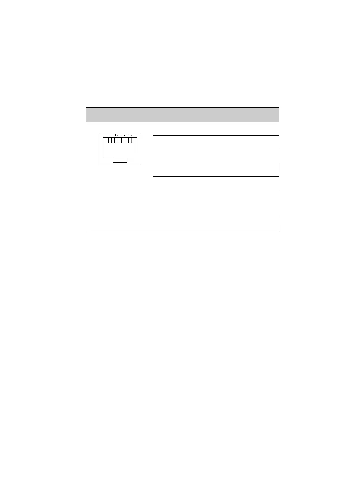
Outline Pin Pin function Wire color
1 Tx+ White/orange
2 Tx- Orange
3 Rx+ White/green
4 Not connected Blue
5 Not connected White/blue
6 Rx- Green
7 Not connected White/brown
8 Not connected Brown
Table 2-19: Ethernet connector, outline and pin assignment

 Loading...


