Installation of the modem
98-175666-D Chapter 2: Installation 2-31
2.6 Installation of the modem
The GX Modem Unit comes in two different variants.
1. 407023A SAILOR GX Modem Unit with CX751 iDirect Core Module
2. 407523A SAILOR GX-R2 Modem Unit with SMB3315 iDirect Core Module
Both modems can be used with all SAILOR GX and SAILOR GX-R2 antenna systems.
2.7 Installation of the 7523A GX-R2 Modem Unit
(SMB3315)
The following sections describe how to install and connect the 407523A modem to the
BDU.
2.7.1 Interfaces of the 407523A GX Modem Unit
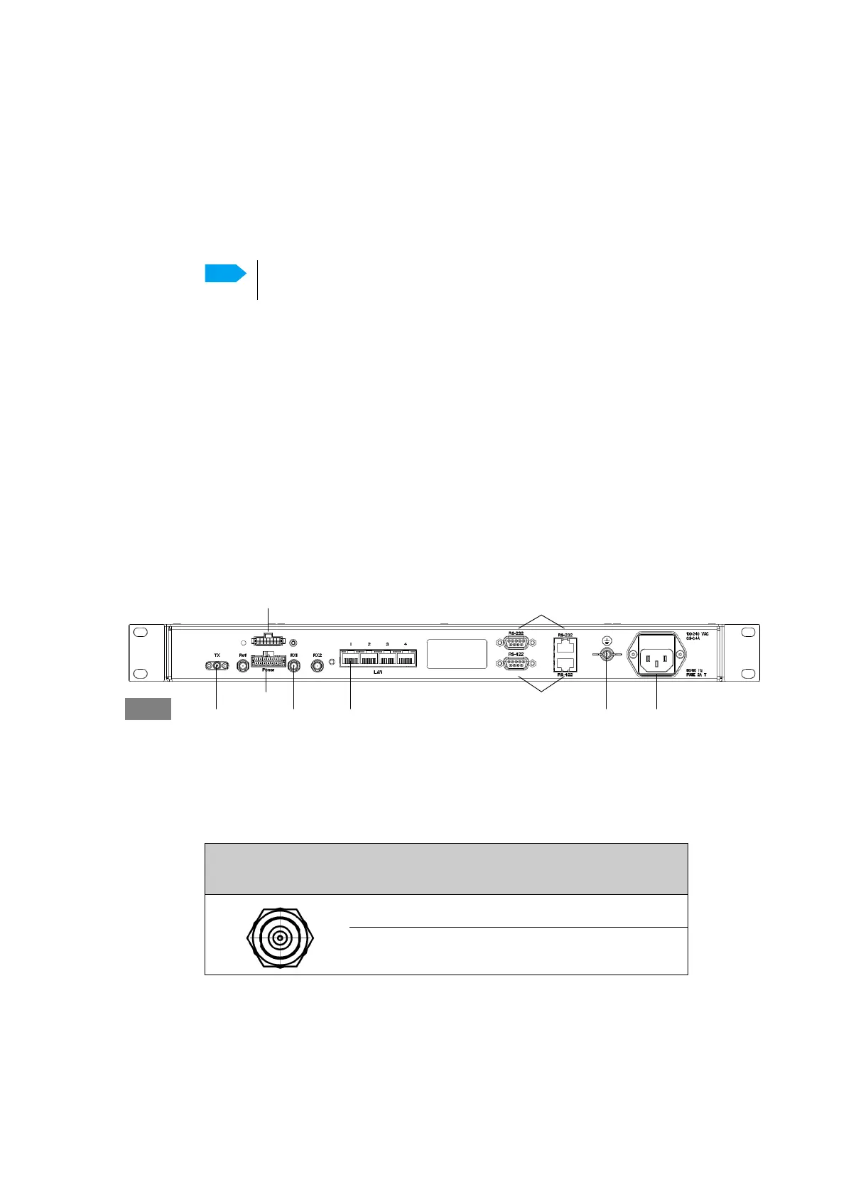
Connector panel
The following figure shows the connector panel of the modem.
Rx In and Tx Out connectors
The modem has an Rx In and a Tx Out connector. Use these connectors to connect the
BDU to the modem.
Note
For information on installation of a dual modem system, see Installation on
page C-6
Figure 2-29: Connector panel of the modem (407523A)
Control via BDUTx Out Rx In GroundRS-422
RS-232
AC Power
GMU
DC power out
DC power in
Outline
(on the BDU)
Pin
number
Pin function
1 Inner conductor: 50 MHz clock, Rx/Tx
2 Outer conductor: GND (Shield)
Table 2-20: F connector, Rx and Tx, outline and pin assignment

 Loading...


