Installation of the 7023A GX Modem Unit (CX-751)
98-175666-D Chapter 2: Installation 2-36
LAN connectors
The modem has several Ethernet connectors (type RJ45). Port 1 connects to the BDU
and is used for modem control. The other ports are not used. The maximum cable
length per connection is 100 m. The Ethernet cable type must be CAT5, shielded. For
outline and pin allocation see LAN connectors on page 2-30.
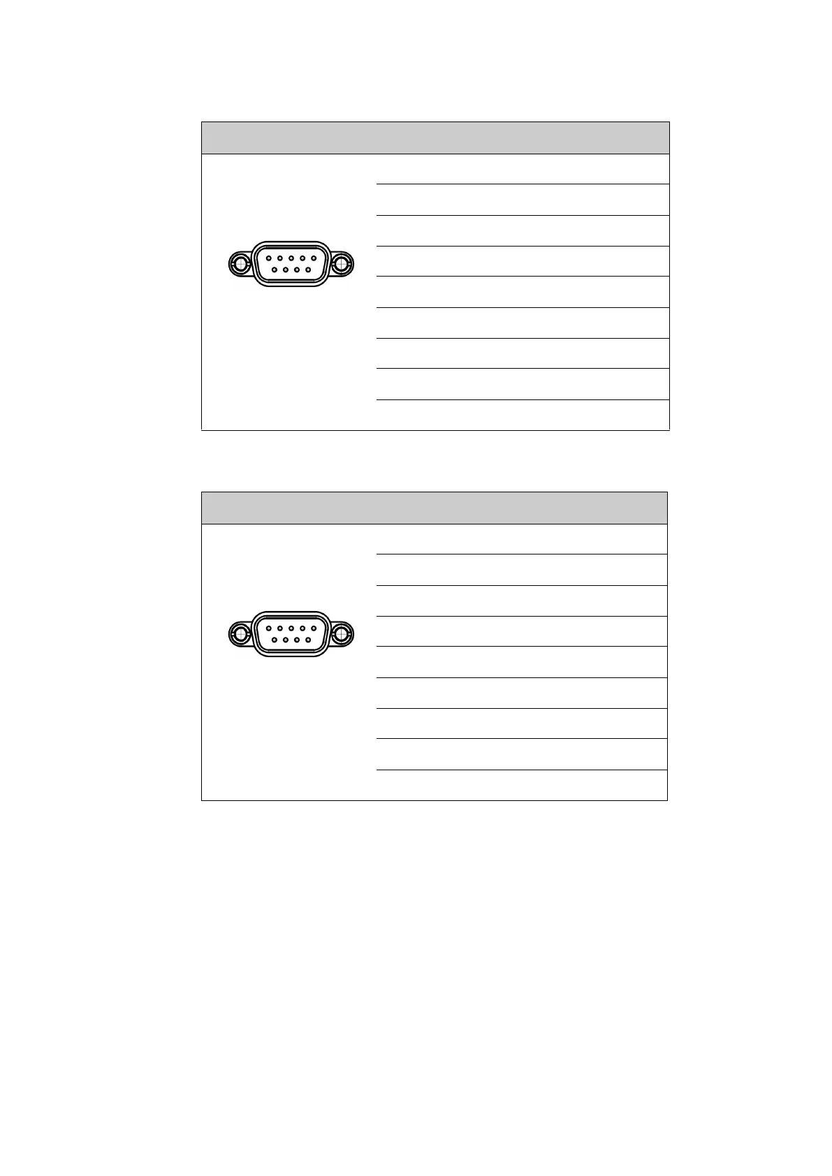
Outline (on the modem) Pin Pin function
1 Not connected
2 BUC TXD
3 BUC RXD
4 Not connected
5 GND
6 Power good
7 GMU reset
8 Temperature out of range
9 Core module RSSI
Table 2-26: RS-232 connector, male, outline and pin assignment, modem
Outline (on the modem) Pin Pin function
1 GND
2 Key-line P
3 Reset P
4 GND
5 GND
6 Not connected
7 Key-line N
8 Reset N
9 Not connected
Table 2-27: RS-422 connector, male, outline and pin assignment, modem
1 5
6 9
1 5
6 9

 Loading...


