Overview
18 Block Up Converter Systems 6700/6900 series User Guide
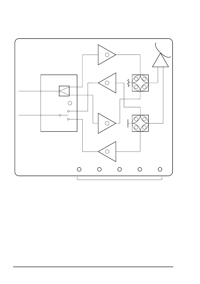
Figure 9: Control panel on the redundancy controller
LED indicators
The control panel of the redundancy controller has groups of
LEDs that indicate the status of the redundancy system and its
fuses. The colours and functions of these LEDs are described
in Table 12 on page 60.
Voltage
Selection
BUC 1
LNB 1*
BUC 2
LNB 2*
Status
Rx IF
Tx IF
Redundancy
Controller
Remote
Controller BUC 1 BUC 2 LNB 1* LNB 2*
BUC
Switch
LNB
Switch*
* Not used in transmit-only systems
Fuse status LEDs