Setting up and operating the BUC system
60 Block Up Converter Systems 6700/6900 series User Guide
The control panel of the redundancy controller has groups of
LEDs that indicate the status of the redundancy system and its
fuses.
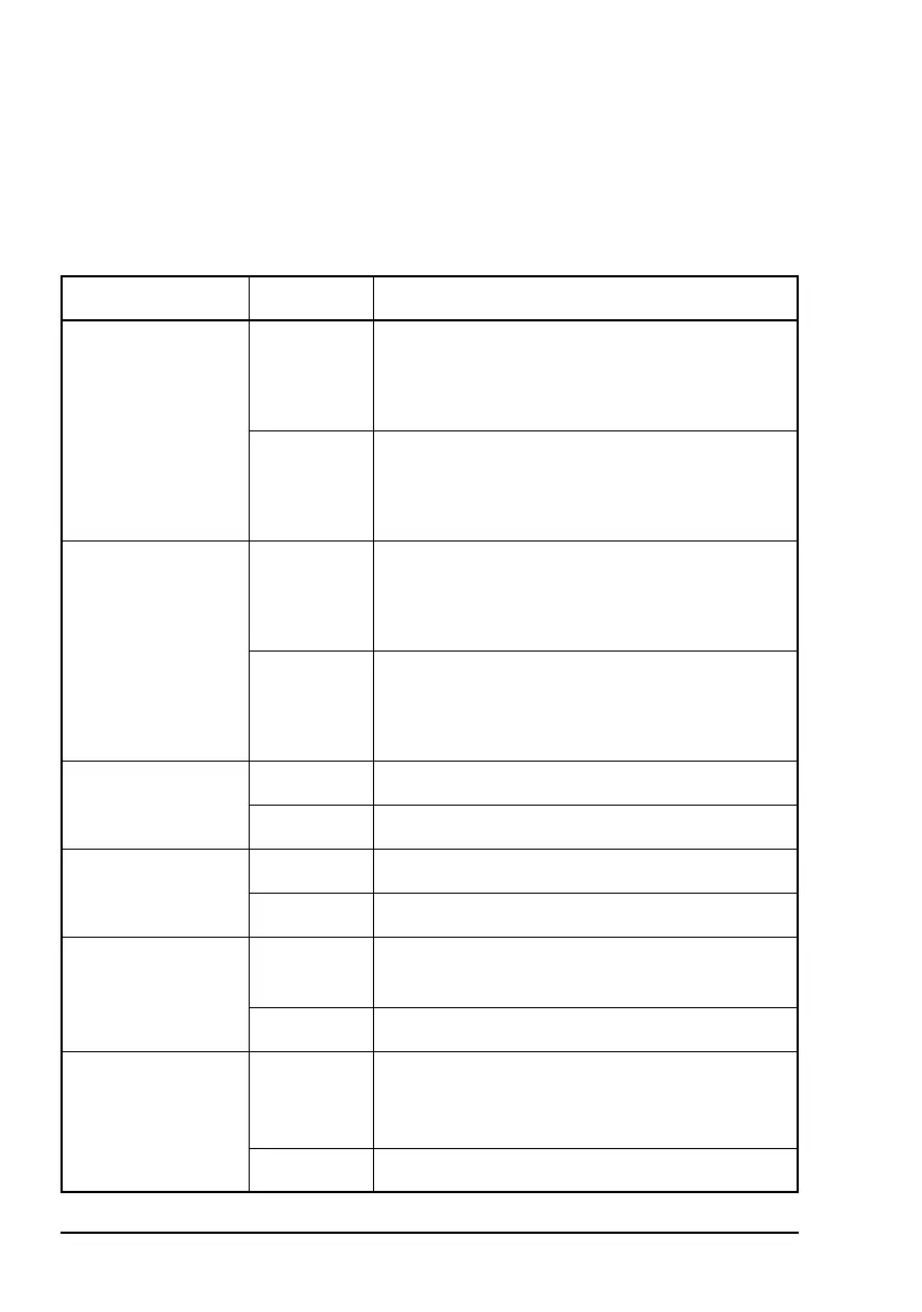
Table 12: LED indicators on the control panel of the
redundancy controller
LED Colour Indicates...
BUC 1 green BUC 1 is OK
In a high-power BUC system, the BUC and
high-power SSPA in Stream 1 are OK
red BUC 1 or LNB 1 is faulty
In a high-power BUC system, the BUC, high-
power SSPA or LNB in Stream 1 is faulty
BUC 2 green BUC 2 is OK
In a high-power BUC system, the BUC and
high-power SSPA in Stream 2 are OK
red BUC 2 or LNB 2 is faulty
In a high-power BUC system, the BUC, high-
power SSPA or LNB in Stream 2 is faulty
LNB 1 green LNB 1 is OK
red LNB 1 is faulty
LNB 2 green LNB 2 is OK
red LNB 2 is faulty
BUC Switch green BUC transmit waveguide switch is OK (LED
pairs indicate switch position)
red Switch is faulty (all four LEDs are red)
LNB Switch green LNB receive waveguide or combined
transmit/receive switch is OK (LED pairs
indicate switch position)
red Switch is faulty (all four LEDs are red)