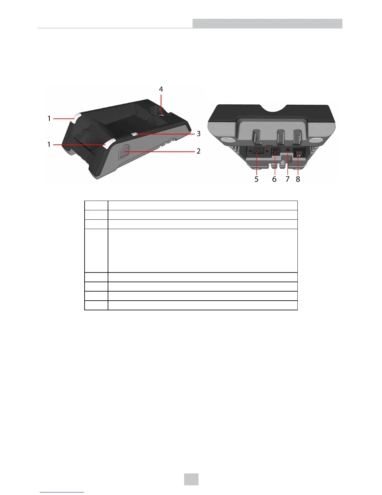
Physical Layout of the Base Station
DMA-IBASE-01
1 Base station status indicators
2 Spare battery charger
3 Spare battery charger status indicator
4
Connection point with the reader:
l pairing reader and base station
l non-wireless communication
l charging
5 RS-232
6 USB
7 Power plug (24V, max. 13W)
8 Ethernet (with optional Class 3 PoE power)
Base station status indicators:
l Power: RED = base powered / BLINK = wrong reader in base
l Communication: BLUE = Wireless link / BLINK = Wireless communication
l Cradle connections: GREEN = reader properly inserted / BLINK = cradle USB interface communication
9
Getting Started