• Using the 12V power supply, connect the DC coaxial plug into the “12V ⎓ 3A” coaxial power jack of the
UFC.
• Using an AC power cord, connect the 12V power supply to a switched AC power source.
• Connect the Ventilation Pump to the same switched AC power source.
The Ventilation Pump should never be switched ON unless its associated UFC is also switched
ON.
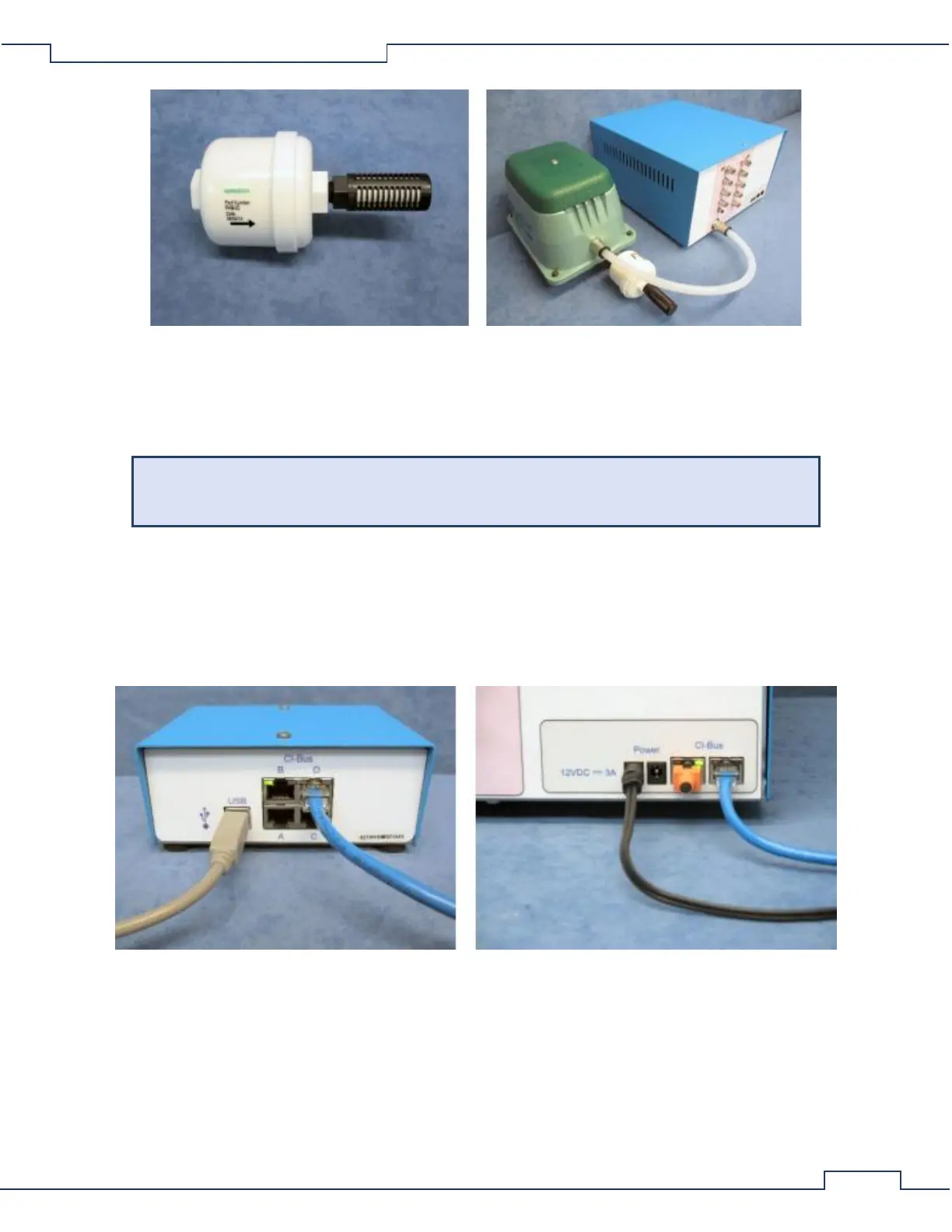
For all UFCs:
• Attach the first UFC to the CI-Bus by connecting any free port from the CI-Bus Hub to one of the ports
of the UFC using an appropriate length ethernet cable.
• Attach additional UFCs to the free port of the previous one in a daisy-chain fashion.
• Place a CI-Bus Terminator into the free port of the last UFC in the daisy-chain.
3.2 Gas Sensor Chain Setup
3.2.1 Gas Sensor Chain Overview
In preparation for measurement, one of four gas sources: a sample from the animal cage, the zero or span
calibration gas, or reference, is dried, metered and passed sequentially through serially connected gas sensors.
Each sensor reports the concentration of a particular gas as a percentage. The gas sensors cabinets are placed
locally to each other and central to all cages of the system, typically on a cart or flat working surface. Below is a