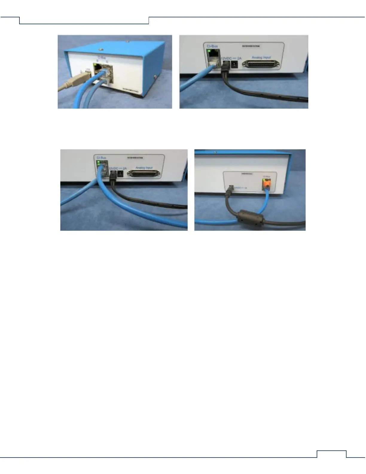
• Attach the Oxygen Sensor to the CI-Bus by connecting the free port of the UGC to one of the free ports
of the Oxygen Sensor.
• Place a CI-Bus Terminator into the free port of the Oxygen Sensor.
3.7 Zirconia Oxygen Sensor Setup
3.7.1 Placing the Components
The components of the Gas Sensor Chain are easy to assemble. A working surface that averages 1.0m x 0.5m
(40” x 20”) is required. It would be best if there is access to the front, rear, and right sides of the working
surface. The components are best placed as follows from the right (the side edge of the working surface) to the
left: Filter Columns, Universal Gas Conditioner, and the Zirconia Oxygen Sensor. Each CLAMS/Oxymax system
ships with a detailed schematic drawing detailing the expected connections for that system. Typically, the color
of each port indicates the typical color of tubing for connection. The following sections detail the typical
connections for each component of the system.