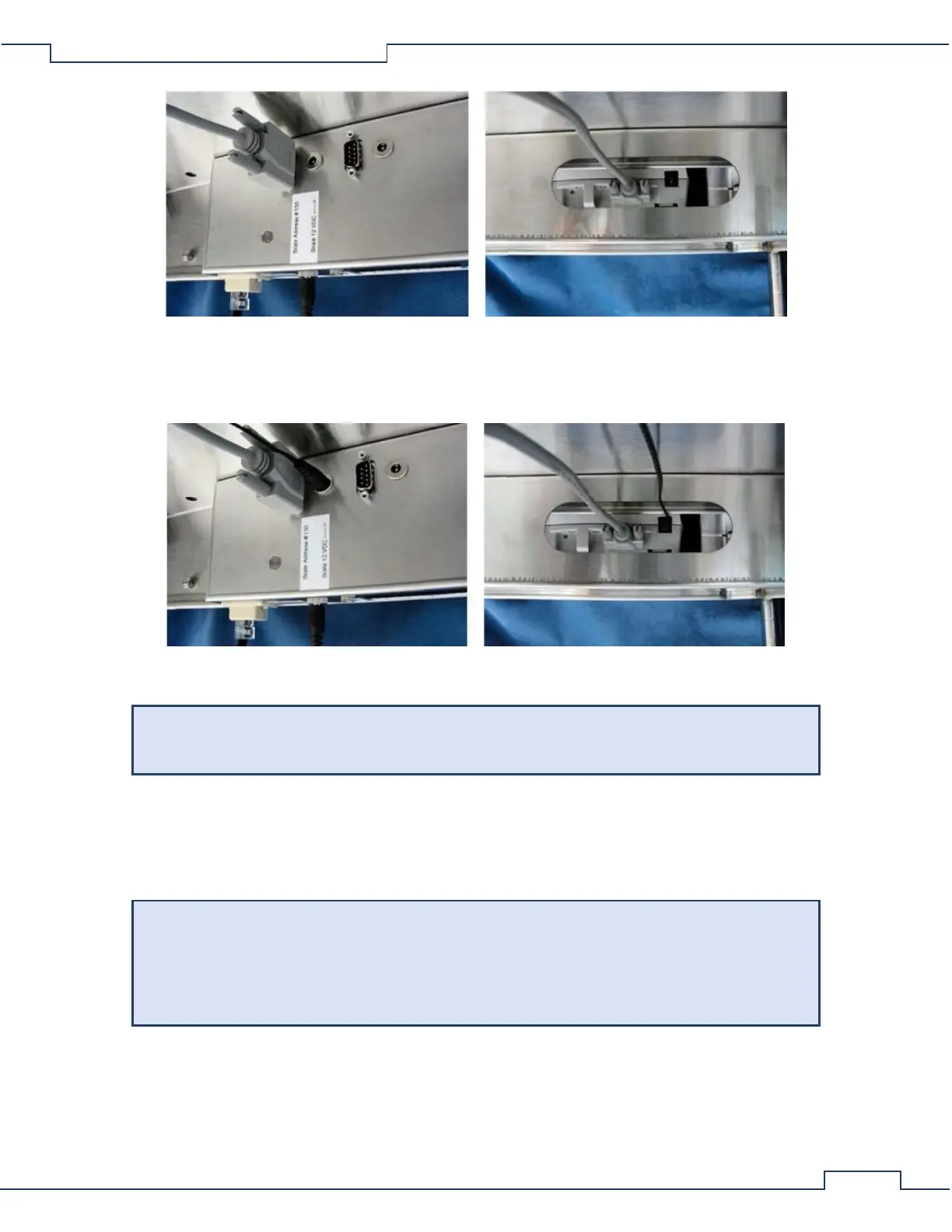
• Using the coaxial DC cable, connect the labeled “12 VDC” port “Scale 12 VDC” of the CLAMS interface
board to the “Power Supply” port of the mass scale. Again, be sure to pass the cable through the
obround cutout as shown.
Correct additional scales to their respective labeled ports of the CLAMS interface boards.
CLAMS Interface Boards can sometimes have more ports than necessary for a given system.
The ports needed for the designed system are usually labeled.
4.3 Load Cells
The load cell for feed monitoring is contained within the lower feeder assembly and data transmission is via
the CI-Bus.
Handle with Care
At no time should the base unit rest upside-down such that the load cells act as a support. This
will permanently damage the load cells. To avoid damage, always orient the base unit suck
that the plastic feet act as the support during cage disassembly and cleaning procedures.
The load cell of the feeder assembly is permanently fixed between the food tray holder and factory adjusted
anchor assemblies pictured below.