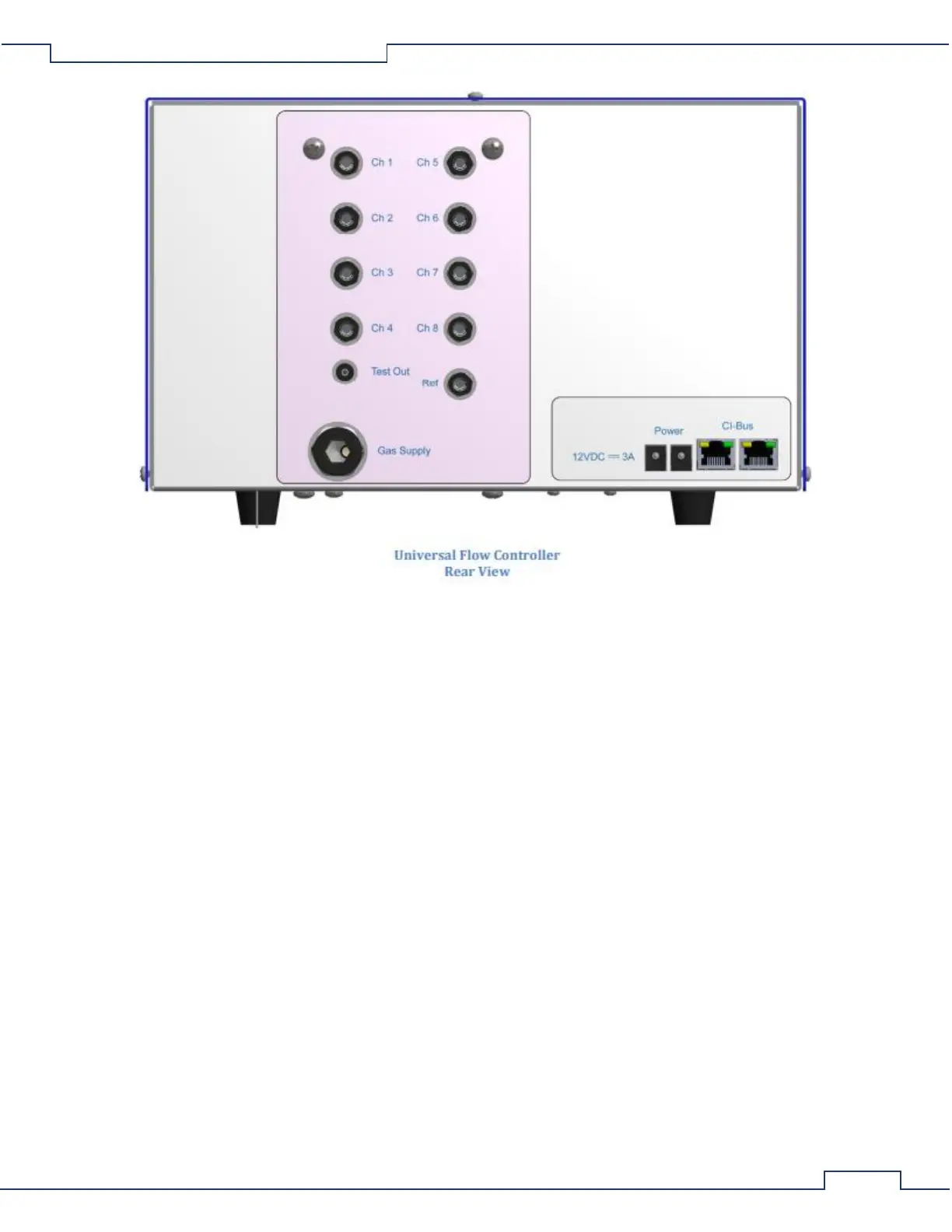
• CH [1:8] & Ref – The ports for connection of the particle-filtered and restricted 1/4" air supply lines
from each cage in the system plus the reference cage.
• Test Out – The output port for gas sampling.
• Gas Supply – The port for connection to an external air-supply ventilation pump.
• 12VDC ⎓ 3A – DC coaxial jack for connection to a suitable power supply.
• CI-Bus – Two (2) ports for connection to the CI-Bus.
• Power – An indicator (typically green) on the top right corner of the left-most CI-Bus port which
indicates connection to DC power.
• Rx – An indicator (typically yellow) on the top left corner of the right-most CI-Bus port which indicates
the UFC is transmitting data.
• Tx – An indicator (typically green) on the top right corner of the right-most CI-Bus port which indicates
the host computer is transmitting data.
3.1.3 Ventilation Pump
A Ventilation Pump is paired with each Universal Flow Controller (UFC) to provide the vacuum pressure and
flow necessary to ventilate all the air supply lines and cages. Typically, the pump is a HIBLOW, model 40 or 80.
The following details the connections found on the Ventilation Pump: