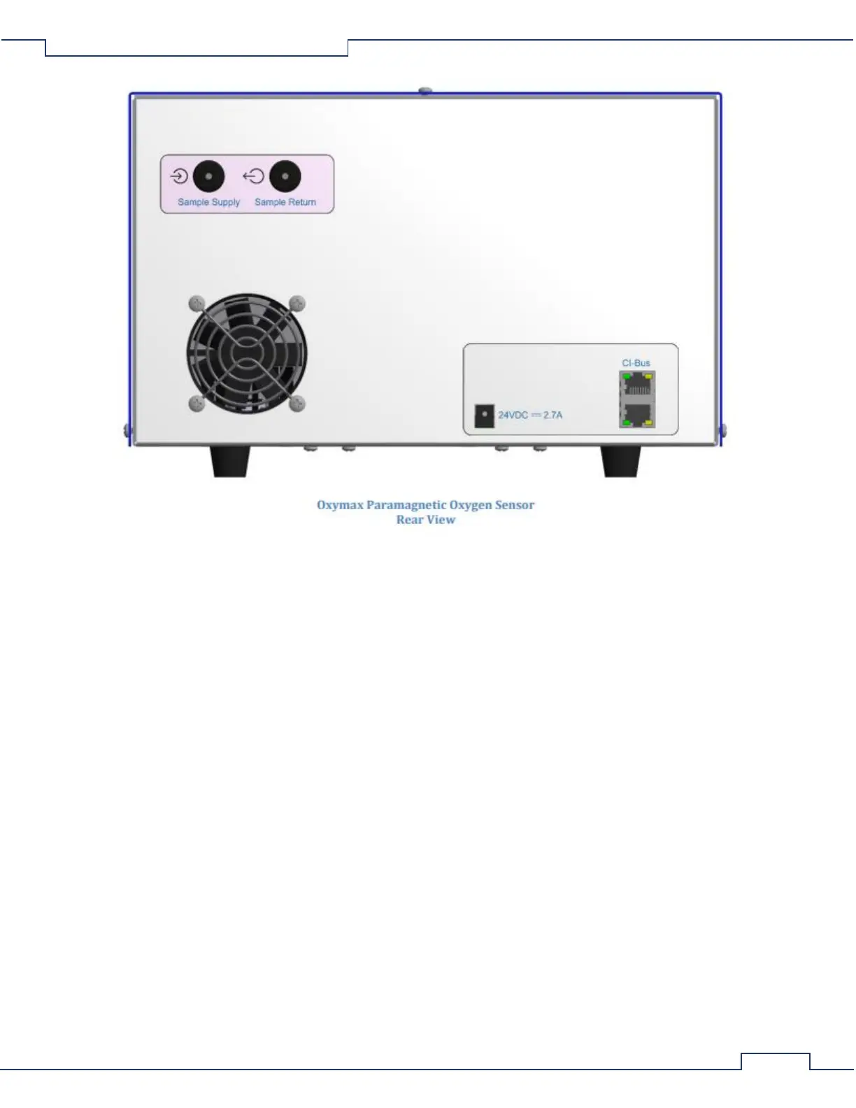
1. Sample Supply – The input port for connection from the UGC’s Sample Supply port.
2. Sample Return – The output port for connection to the next gas sensor or to the UGC’s “Sample
Return” port.
3. 24VDC ⎓ 1A – DC coaxial jack for connection to a suitable power supply.
4. CI-Bus – Two ports for connection to the CI-Bus.
5. Power – An indicator (typically green) in the top left corner which indicates connection to DC power.
6. Tx – An indicator (typically green) in the bottom left corner which indicates the host computer is
transmitting data.
7. Rx – An indicator (typically yellow) on the bottom right corner which indicates the Oxygen Sensor is
transmitting data.
3.6 Chemical Oxygen Sensor Setup
3.6.1 Placing the Components
The components of the Gas Sensor Chain are easy to assemble. A working surface that averages 1.0m x 0.5m
(40” x 20”) is required. It would be best if there is access to the front, rear and right sides of the working
surface. The components are best placed as follows from the right (the side edge of the working surface) to the
left: Filter Columns, Universal Gas Conditioner, and the Chemical Oxygen Sensor. Each CLAMS/Oxymax system
ships with a detailed schematic drawing detailing the expected connections for that system. Typically, the color
of each port indicates the typical color of tubing for connection. The following sections detail the typical
connections for each component of the system.