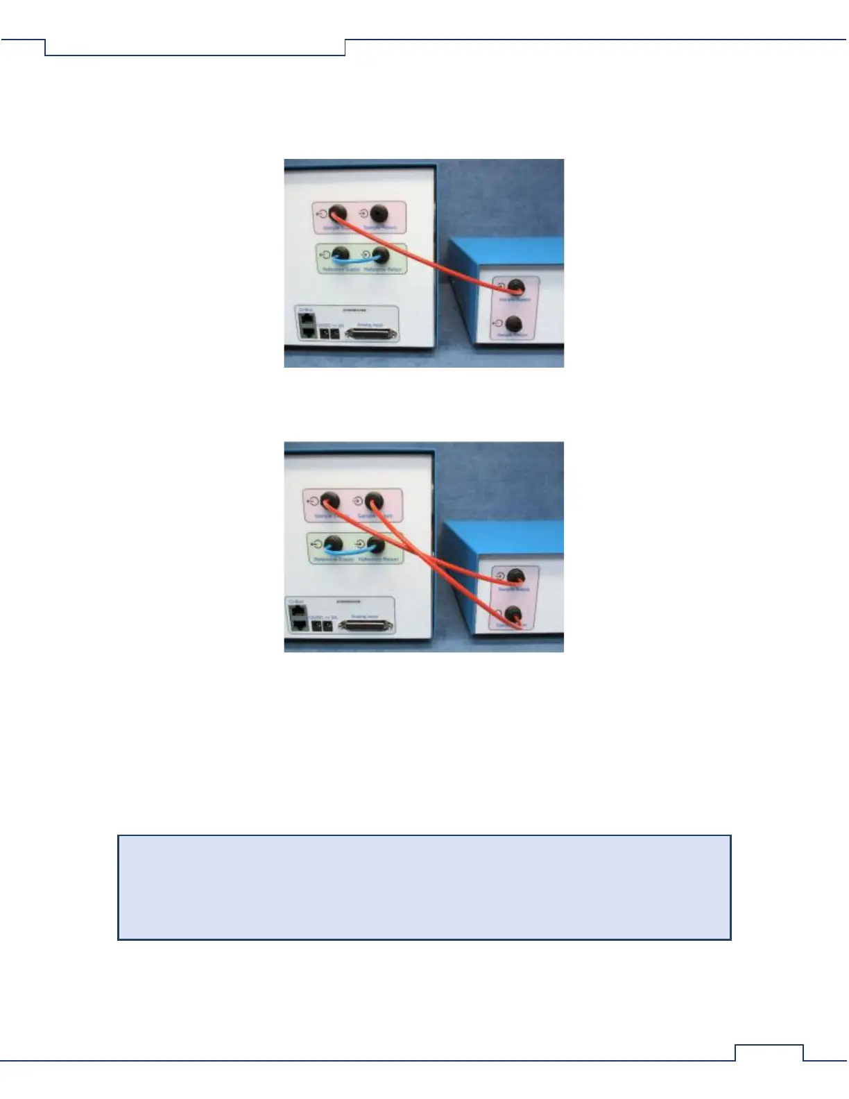
Sensor Sample Tubing Connections
• Using an appropriate length of 1/8” red air line, connect the output “Sample Supply” port of the UGC
to the input “Sample Supply” port of the Oxygen Sensor.
• Using an appropriate length of 1/8
th
red air line, connect the output “Sample Return” port of the
Oxygen Sensor to the input “Sample Return” port of the UGC.
Electrical Power Connections
• Using the 24V power supply, connect the DC coaxial plug into the “24V ⎓ 1A” coaxial power jack of the
Chemical Oxygen Sensor.
• Using an AC power cord, connect the 24V power supply to an AC power source.
• Using the 12V power supply, connect the DC coaxial plug into the “12V ⎓ 2A” coaxial power jack of the
UGC.
• Using an AC power cord, connect the 12V power supply to an AC power source.
The UGC should only be connected to an active AC power source after all the gas ports have
been properly connected with particle filters where appropriate. This will prevent debris from
being drawn into the unit where it may restrict and clog the internal faculties of the Universal
Gas Conditioner.
CI-Bus Connections
• Attach the UGC to the CI-Bus by connecting any free port from the CI-Bus Hub to one of the ports of
the UGC using an appropriate length ethernet cable.