FLASH: The sample temperature is moving toward it’s respective operating setpoint.
ON: The sample temperature is steady and reports valid measurements.
5. Sensor Fault – A red light which indicates the status of the sample heater circuitry.
OFF: The heater circuitry is operating normally.
FLASH: A fault has been detected within the heater circuitry.
6. Sensor Compartment Door – A push-to-open and close door which conceals the compartment for the
oxygen sensor receptacle and connector.
7. Sensor Connector – A four or two pin connector used to connect the electrical output of the oxygen
sensor to the measurement circuitry.
8. Sensor Receptacle – A temperature-controlled receptacle for housing and interfacing the oxygen
sensor to the sample gas.
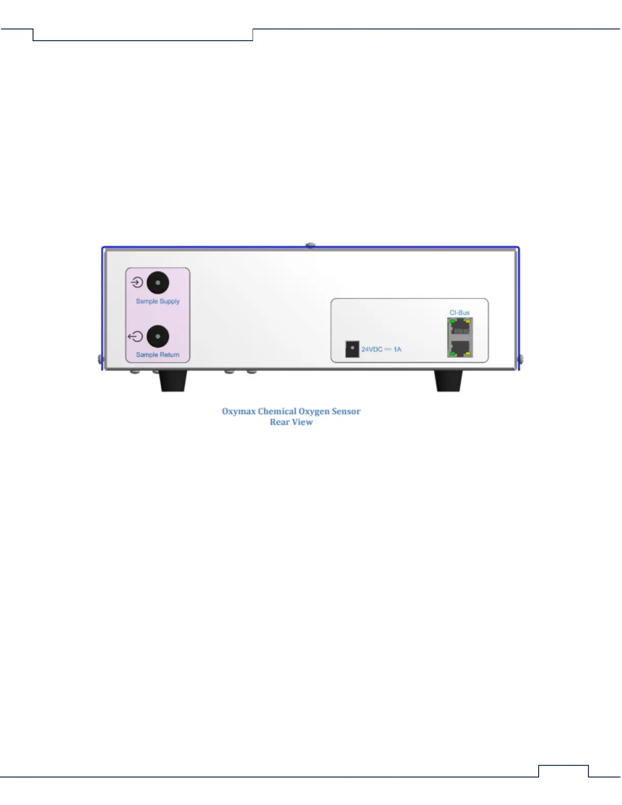
1. Sample Supply – The input port for connection from the UGC’s Sample Supply port.
2. Sample Return – The output port for connection to the next gas sensor or to the UGC’s “Sample
Return” port.
3. 24VDC ⎓ 1A – DC coaxial jack for connection to a suitable power supply.
4. CI-Bus – Two ports for connection to the CI-Bus.
5. Power – An indicator (typically green) in the top left corner which indicates connection to DC pwer.
6. Tx – An indicator (typically green) in the bottom left corner which indicates the host computer is
transmitting data.
7. Rx – An indicator (typically yellow) on the bottom right corner which indicates the Oxygen Sensor is
transmitting data.