• Position the assembly near the UGC and use an appropriate length of 1/8” red air line to connect the
down-stream port of the filter (the end with the particle filter) to the “Sample” port of the UGC.
• Using an appropriate length of the 1/8” red air line, connect the up-stream port of the filter (the end
with an ammonia trap) to the “Test Out” port of the UFC.
Assembling the Zero Gas Source
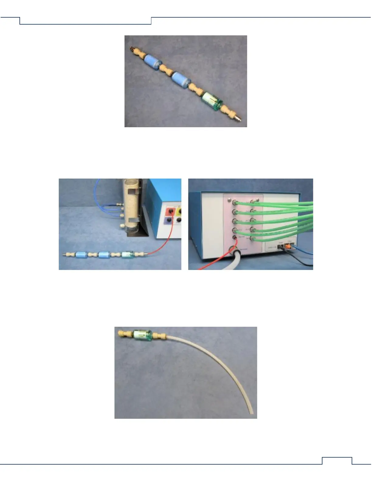
• Locate the Zero Gas Filter Assembly. It consists of a Parker/Balston filter with a 1/4” union connector
over each end and a short section of 1/4” natural air line connected to the down-stream port.
• Connect the 1/4” natural air line of the Zero Gas Filter Assembly to the “Zero Gas” port of the UGC.