Assembling the Reference Source
• Using an appropriate length of 1/8” blue air line, connect the source of reference gas (typically from a
tee fitting placed in the air supply line of the Reference Cage) to the Input “Reference” port of the
UGC.
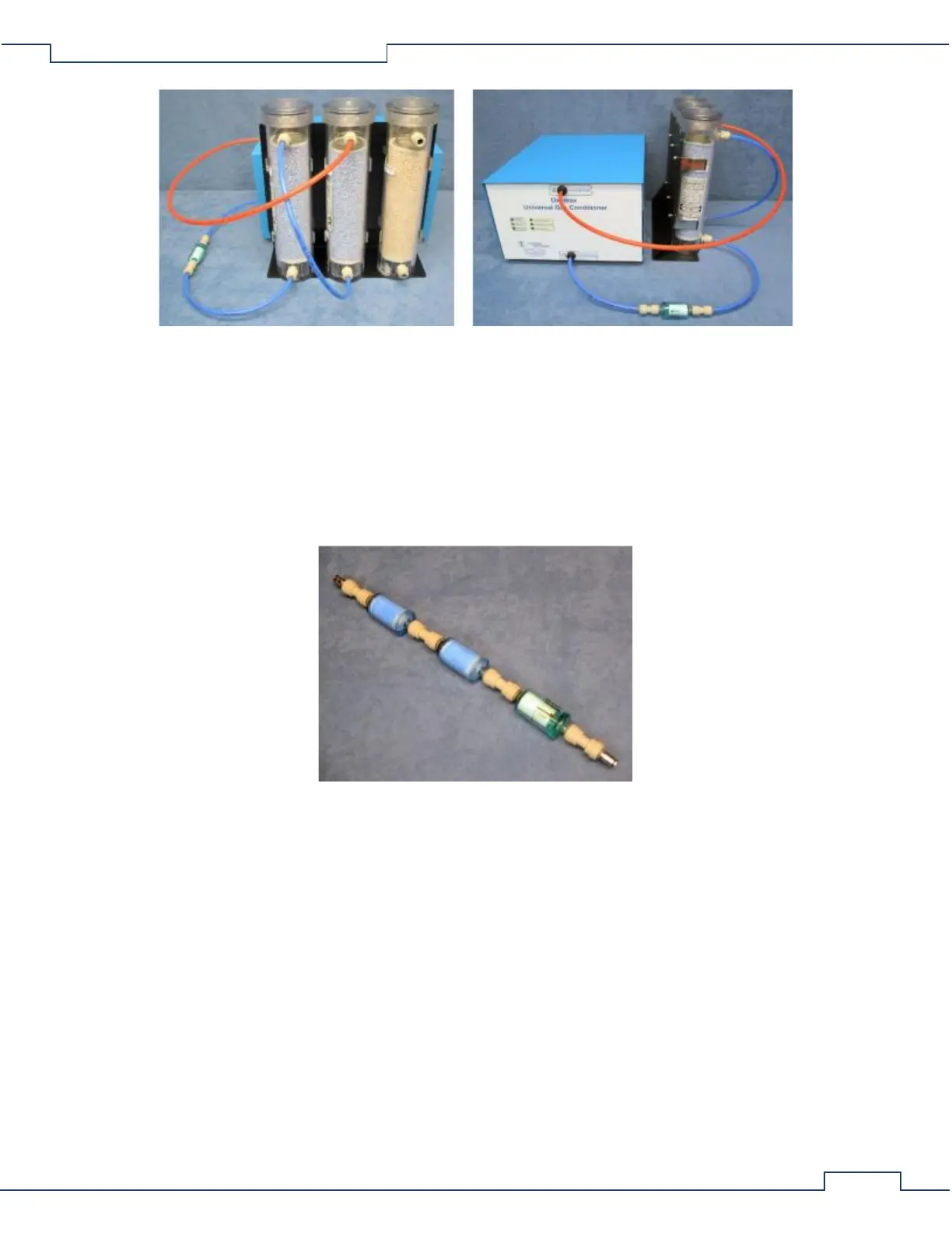
Assembling the Sample Line Filter
• Locate the Sample Line Filter Assembly. It consists of two blue ammonia traps and one Parker/Balston
particle filter all serially connected using 1/4"union connectors with 1/8” air line ports on each end.
• Position the assembly near the UGC and use an appropriate length of 1/8” red air line to connect the
down-stream port of the filter (the end with the particle filter) to the “Sample” port of the UGC.
• Using an appropriate length of 1/8” red air line, connect the up-stream port of the filter (the end with
an ammonia trap) to the “Test Out” port of the Universal Flow Controller.