InteliVision 5 - Global Guide
36
Note: For the information how to connect InteliVision 5 to the controller go to the Installation guide or Terminals
and dimension chapter.
RS 485 terminators have to be used to assure proper functionality.RS 485 port is galvanic separated and IV5
might be use for communication for long distance up to 1000m.
4.2 How many InteliVision 5 can be used
Unit Number of displays Terminal address
IS2GAS 4 1,2,3,4
IDDCUMarine 3.0.0 5 1,2,3,4,5
IG-NT(C) –BB 3 1,2,3
IS-NTC – BB 4 1,2,3,4
IM-NT-BB 2 1,2
IG-NT(C) 1 2
IS-NT-BB 3 2,3,4
IM-NT 1 2
For how to set up InteliVision 5 address see How to Connect InteliVision 5 to IGS-NT on page 35.
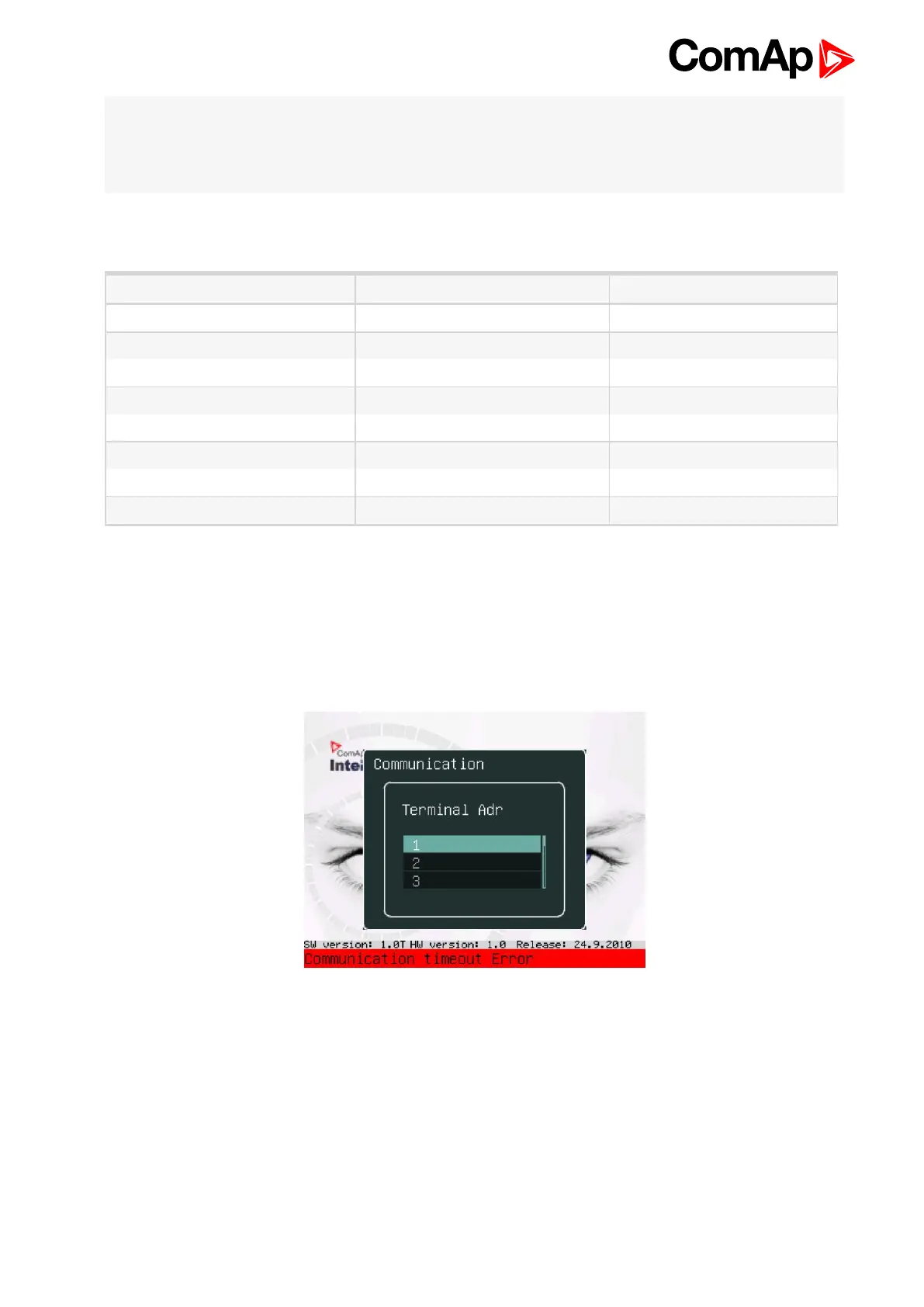
4.3 Communication Error
Communication error occurs when no control unit is connected to the display or communication is interrupted. In
that case the following screen appears:
When the communication between unit and display is fixed, the red stripe disappears and InteliVision 5
initializes communication with the unit.
The control unit is identified by InteliVision 5 and only valid numbers of terminal addresses are displayed. For
the maximum number of connected InteliVision 5 see How many InteliVision 5 can be used on page 36.