Appendices
140
C3M2-OM-EN-02
Note
Port ‘G’ Thread Specification - M12x1.5 - 12mm deep
Max tightening torque 50Nm / 37ft.lb
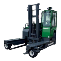
13. Start the engine and read the charge pressure from the gauge.
14. The pressure should read between 22 - 25 bar (320 - 362 PSI) when the engine
is idling.
15. Contact your local service representative or Combilift service if the charge
pressure is outside the specified range.
16. Remove the gauge and refit the hydraulic adapter (ensure the adapter is clean
and undamaged) and hose securely. Apply a suitable thread sealant to the
threads on the adapter before refitting.
17. Clean up any oil spills immediately.
7.2 Valve Chest Pressure Settings
To check the valve chest pressure settings:
1. Park the truck in an area with
adequate space and headroom to
operate all mast functions through the
full extent of their range.
2. Extend the reach to allow access to the
pressure test point (A) on the valve
chest.
3. Lower the mast fully and tilt the mast
forward fully.
4. Turn the ignition key switch to the ‘0’ off
position, then remove the key.
5. Wait until all components in the vicinity
of the test point are cool enough to
touch or wear head resistant gloves
before proceeding.
6. Enter the area between the left-hand and right-hand platforms behind the
mast. Ensure all surfaces are clean and dry and take great care to avoid
slipping!
7. Clean and dry the test point and the surrounding area thoroughly.
Warning
Ensure that the engine is switched off until the pressure gauge has been
attached.
Ensure there is adequate space and headroom to operate each of the
hydraulic mast/fork functions through the full extent of their range.
A