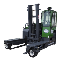
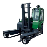
Basic Information
19
C3M2-OM-EN-02
2.4 Principle of Operation
Drive is achieved by means of a hydrostatic pump coupled to an internal combustion
(IC) engine. The engine drives the hydrostatic pump which pumps hydraulic oil
through hoses to hydraulic motors. The trucks drive wheels are mounted on the
hydraulic motors and as the pressurised hydraulic oil passes through the wheel
motors the wheels turn to propel the truck. The engine speed – and therefore the
trucks ground speed - is controlled by a throttle pedal located inside the operator’s
cabin.
Steering is achieved by means of a hydraulic gear pump coupled to an internal
combustion (IC) engine. The IC engine drives the gear pump which pumps hydraulic
oil through a steering orbital unit. When the steering wheel is turned pressurised oil
is fed via the steering orbital to hydraulic steering cylinders to steer the truck.
Lift, reach and tilt along with any other optional auxiliary hydraulic mast/fork functions
are achieved by means of a hydraulic gear pump coupled to an internal combustion
(IC) engine. The IC engine drives the gear pump which pumps hydraulic oil through
hoses to a block of valves. The valves - which are operated using levers or a joystick
located inside the operator’s cabin – allow the pressurised oil to be directed through
hoses to various hydraulic cylinders that are connected to each of the mast/fork
functions. The operating speed of the mast/fork functions may be increased by
pressing the throttle pedal located inside the operator’s cabin.
Forward, reverse, left or right travel may be selected using a four-way direction
switch mounted inside the operator’s cabin. Selecting a direction of travel sends
electrical signals to a set of solenoid actuated hydraulic valves in the steering circuit.
The valves direct the flow of hydraulic oil through the steering circuit to the steering
cylinders to steer the swivel arms to the appropriate position to achieve the desired
travel mode. A solenoid actuated direction control valve directs the flow of oil through
the drive circuit to achieve the desired direction of travel.
The truck is equipped with analogue dash clusters that display information regarding
the trucks operating condition such as the engine coolant temperature, engine oil
pressure, low fuel, steering mode etc.
Park braking is provided by brake units that are integrated into each of the wheel
motors. The park brake is applied by spring force; hydraulic pressure is required to
release the park brake. The park brake is applied and released using a switch inside
the cabin.
An inch brake slows the truck down when partially applied and brings the truck to a
complete stop when fully applied and held on. It works by restricting and blocking the
flow of hydraulic oil through the drive circuit which prevents the wheel motors from
turning. The inch brake is applied by pressing a pedal located inside the operator’s
cabin.