Combilift Ltd C2500-C3000CB O&S Manual
5-17
C2500CB-OM-EN-11
5.13 PLC Details
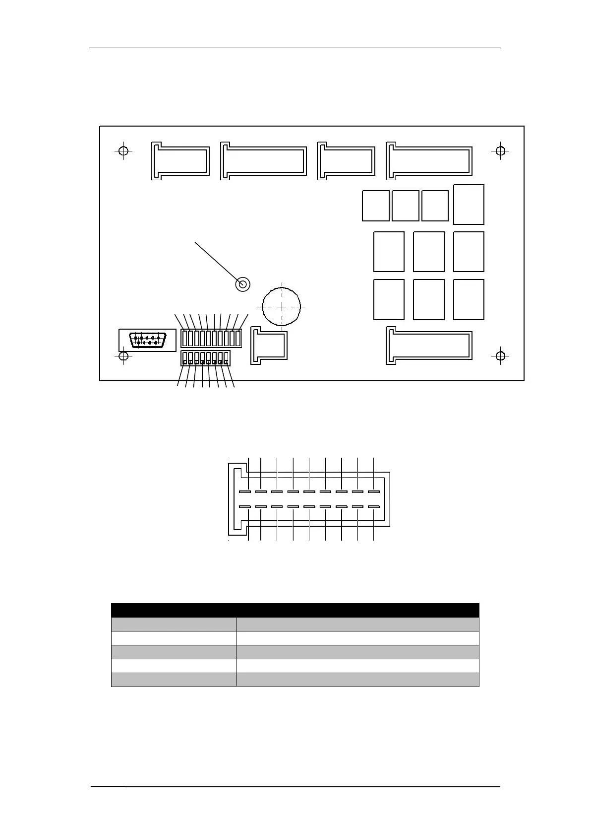
The diagram below shows the layout of the major components of the PLC
board that need to be known in order to correctly find and repair faults.
The pins in each of the plugs on the board are laid out as follows.
The System LED tells the operator what the PLC is doing. The following table
gives an explanation of what the System LED is indicating.
System LED Status Meaning
NoLED NopowerSupplytoPLC
FlashingGreen(Fast) PLCisnotProgrammed
FlashingGreen(Slow) PLCisProgrammed&RunningNormally
StaticGreen PLCisProgrammedbutnotRunning
StaticRed PLChasFailed(ReplacePLC)
Each of the plugs has a specific function as do the pins on each plug. The
tables on the following pages give details of the functions on each of the plugs
and the pin associated with each function.
PLUG X4
PLUG X3 PLUG X5.1
PLUG X5.2
LED
12345678910
12345678
DipSwitches
System LED
13 5 7 911131517
18161412108642