44
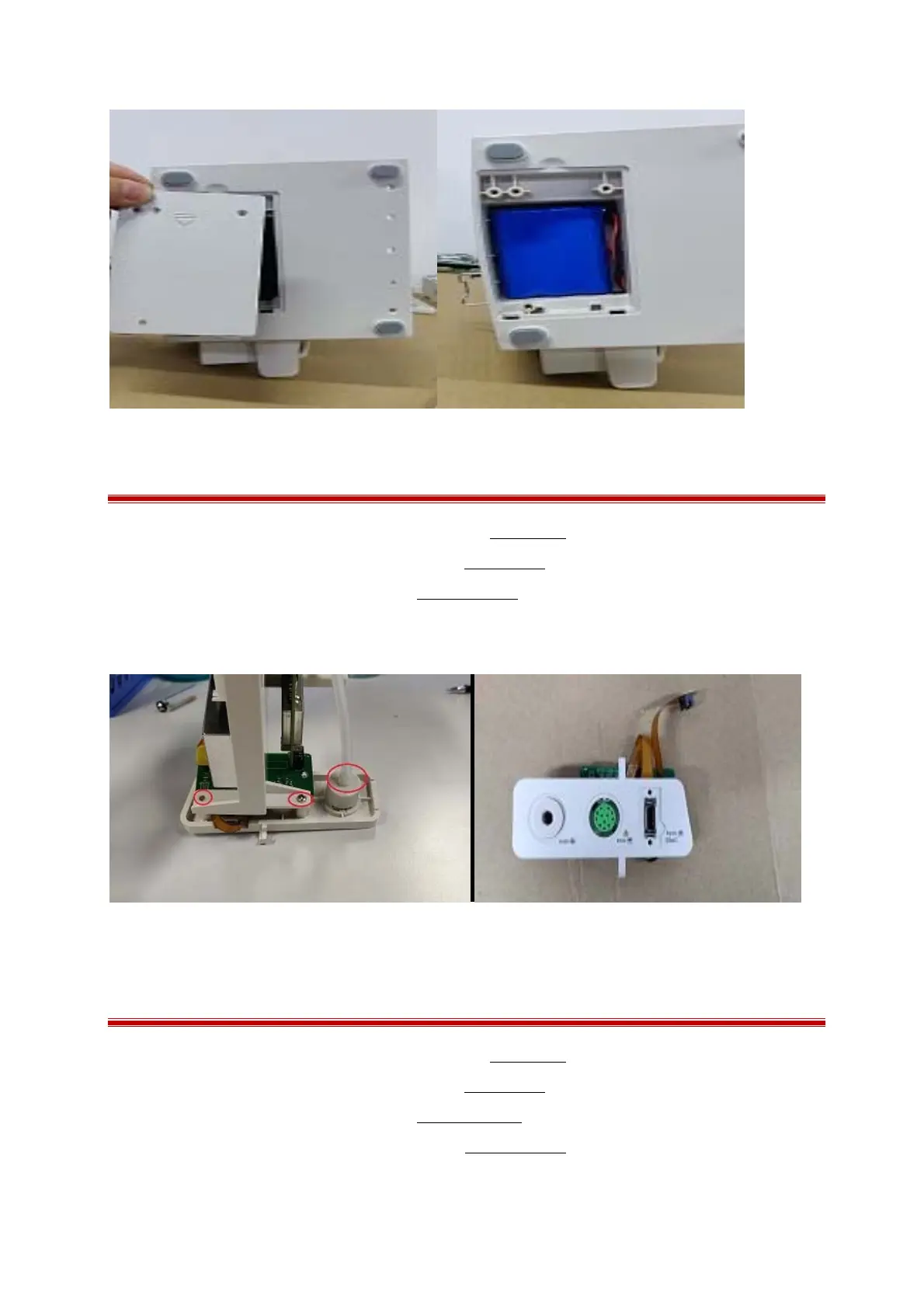
7.12 Removing the side connection board
1 Separating the front and rear housing as described in Chapter 7.2;
2 Removing the power switch board as describe in Chapter 7.9;
3 Remove the function block as describe in Chapter 7.10.1;
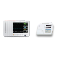
4 Remove the air connection hose and unscrew 2PB3.0×6.0 mm screws and then pull out the side
connection board.
7.13 Removing the DC supply power and SPO2 board
1 Separating the front and rear housing as described in Chapter 7.2;
2 Removing the power switch board as describe in Chapter 7.9;
3 Remove the function block as describe in Chapter 7.10.1 ;
4 Remove the side connection board as describe in Chapter 7.10.3;
5 Unscrew the 6 PB 3.0×6.0mm screws and then take off the board.