ComNav Marine 1420 Autopilot System
Document PN 29010012 V1.3
17
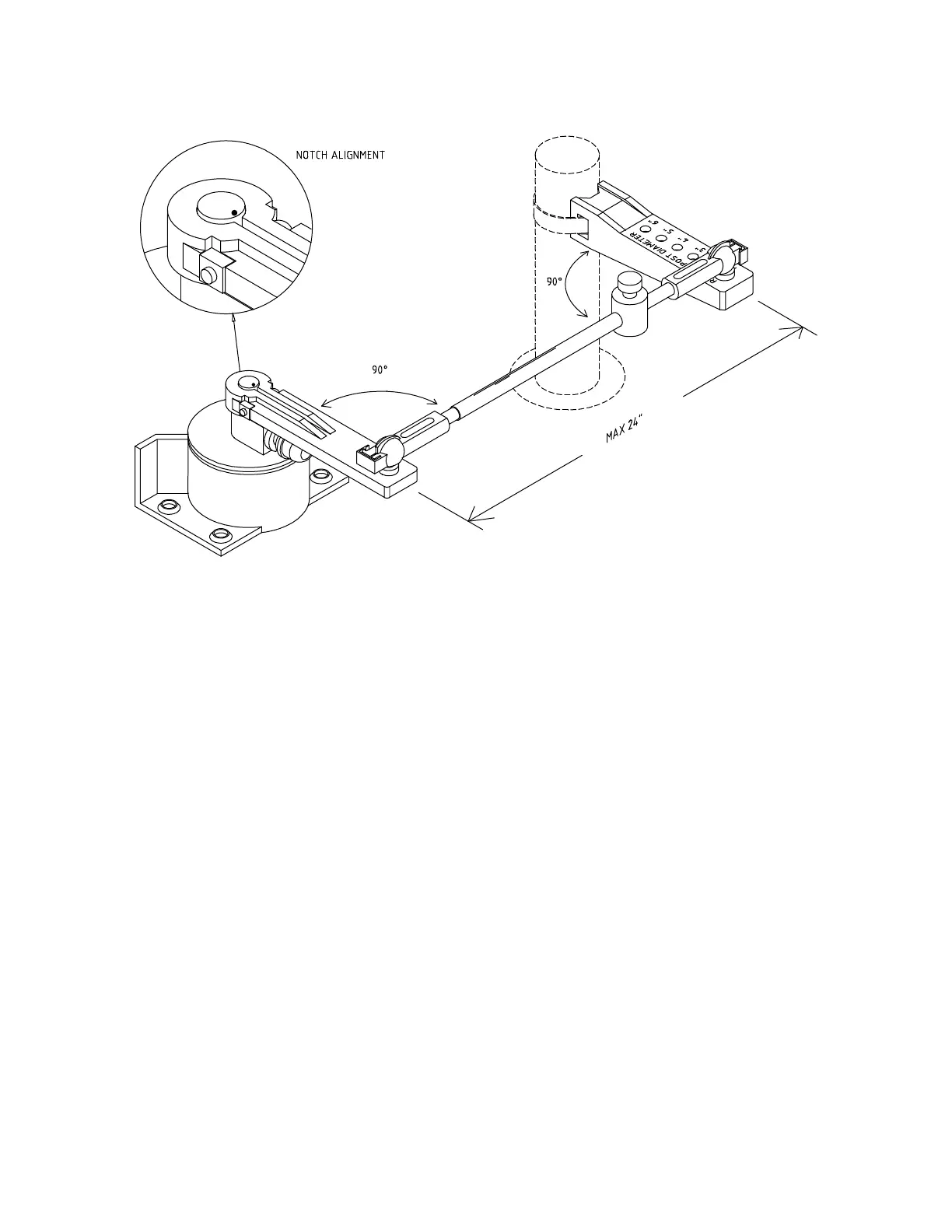
Mounting the Rudder Feedback
To align the Rudder Feedback Arm & the
Rudder Post Arm correctly, you may need
to make a mounting base for the Rudder
Feedback. Such a base must be firm. It
should not flex when the vessel is
moving.
In the diagram above notice that:
• the Rudder Feedback Arm is above
the cable entry gland
• the Linkage sockets are on the top of
the ball joints. Do not mount the ball
joints on the underside of the Arms,
so that the Linkage would “hang”
from the ball joints.
Use the Rudder Feedback as a template
to drill holes in the mounting surface. If
you must drill new holes in the flange at
the back of the Rudder Feedback, drill the
Rudder Feedback flange first, and then
use it as a template to drill holes in the
surface.
Mount the Rudder Feedback so that the
Rudder Feedback Arm and the Rudder
Post Arm:
• are at the same height
• are separated by less than 24”
(60.9 cm) centre to centre
Mount the Rudder Feedback using # 10
(5 mm) screws or bolts of suitable length.
• each makes an angle of 90 degrees
with the Linkage