ComNav Marine 1420 Autopilot System
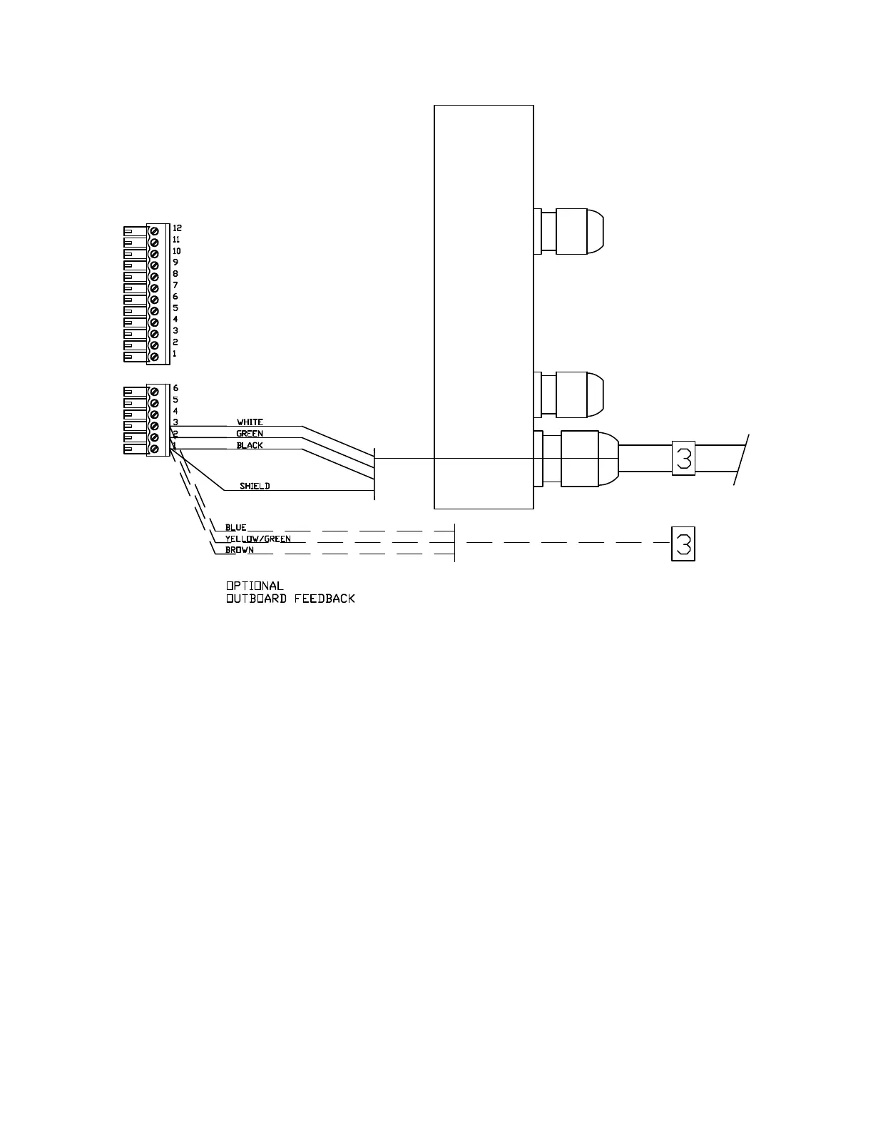
Right Side, Cable 3 (Rudder Feedback) to J7
Connecting the Ground Wire
Left Side Connections
In the Cable 5 diagram below, the Ground
is the green wire. It is connected to the
bolt beside the terminal sockets for the
power connection.
Next, do the left side wiring. Remove the
terminal strips from the left side end
piece.
Apply a “4” wire label to the cable from
the Pump, and pass it and Cable "5"
through the glands in the left side end
cap; wire each cable’s wires to the
terminal strips, as shown in the diagrams
on the following page:
The green wire is connected by removing
one of the nuts and the lock washer from
the bolt. Place the ring terminal on the
end of the green wire over the bolt.
Replace the lock washer. Replace the
nut and tighten it securely.
• Left Side, Cable 4 (Pump Motor)
The other end of this wire should be
connected to the grounding point you
have chosen aboard your boat. See
page 14 for examples of possible
grounding points.
• Left Side, Cable 5 (Power)
Make sure all stripped wire ends are
completely inside the terminal strips.
Document PN 29010012 V1.3
36