ComNav Marine 1420 Autopilot System
GR E E N
RE D
BLACK
BLUE
WH I T E
YE L L O W
SHIELD
GREEN
PINK
GREY
YELLOW
WHITE
BROWN
SHI ELD
Original
Cable
Colours
Al ter na te
Cable
Colours
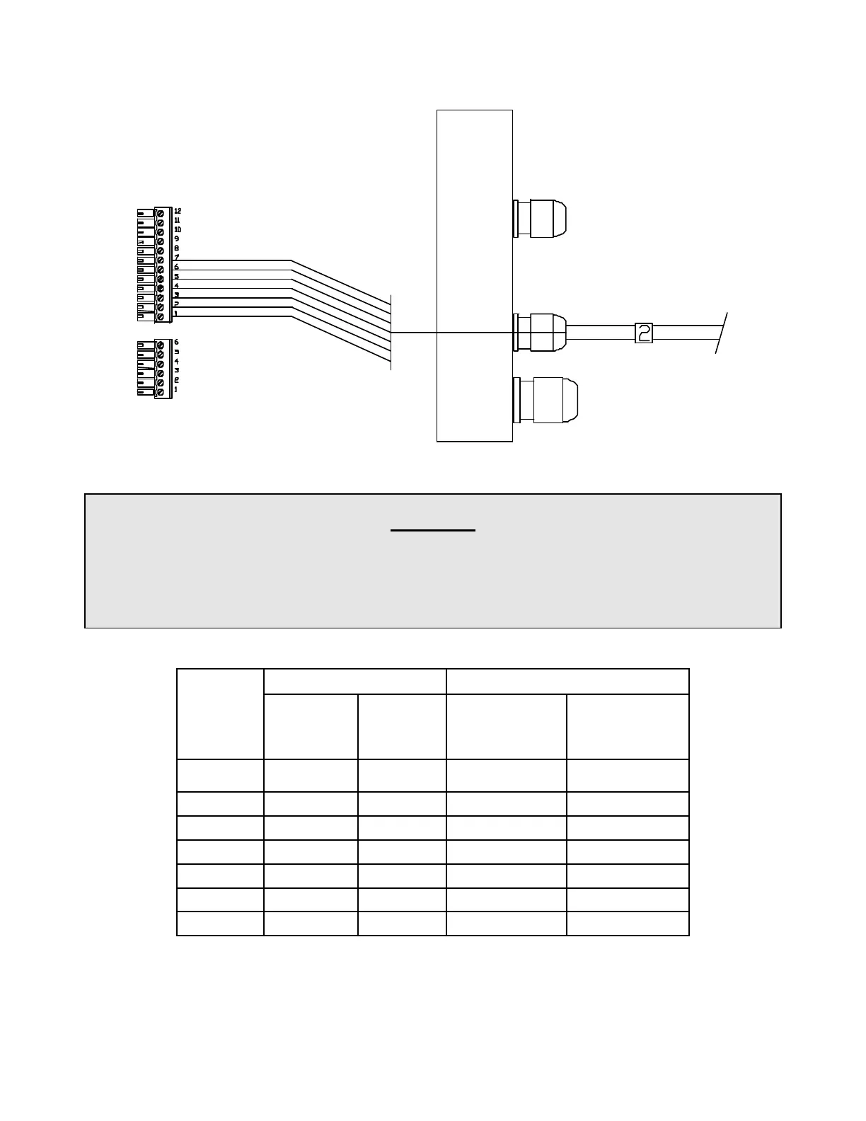
Right Side, Cable 2 (Compass) to J6
Be Careful
The entire stripped end – but no portion of the insulation – of all wires into the terminal strip
plugs must be completely inside the plugs. The stripped ends of wire must not be able to
touch each other.
Every wire must be connected to the correct terminal on its plug!
Connections For Fluxgate Compasses
Cable 2 Signal Function
J6 PIN
Original
Wire
Colours
Alternate
Wire
Colours
ComNav
Fluxgate
Compass
Other
Compass
1 SHIELD SHIELD GROUND GND
2 YELLOW BROWN COSINE
COSINE *
3 WHITE WHITE REF REF
4 BLUE YELLOW SINE
SINE *
5 BLACK GREY DRIVE P2 N/C **
6 RED PINK DRIVE P1 N/C **
7 GREEN GREEN +12V +12V
* If the compass reading is reversed, swap these two wires
** These wires must not be connected to non-ComNav compasses
Document PN 29010012 V1.3
35