ComNav Marine 1420 Autopilot System
Left Side, Optional Navigation Input Connection
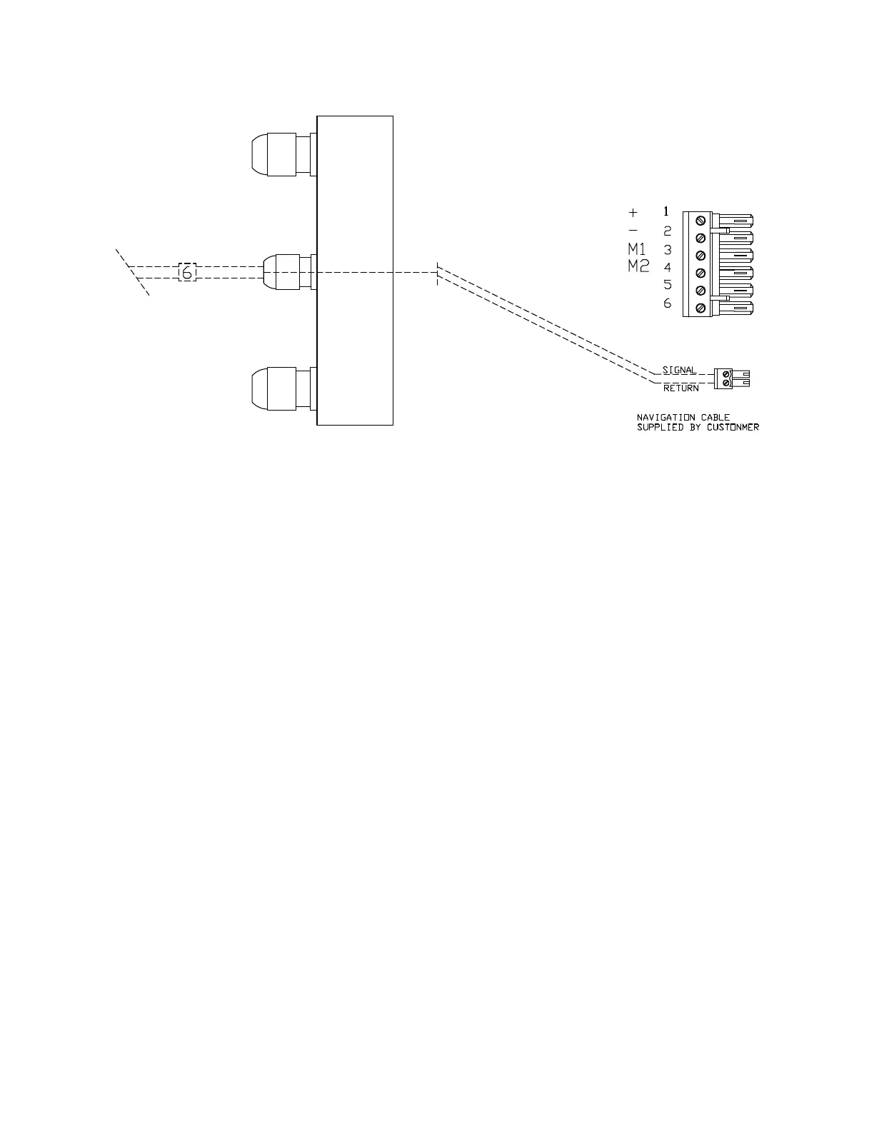
Connecting the Navigation Cable
The optional navigation data input cable
may be connected at this time. Parts for
this are in the Accessory Kit. We do not
supply the cable for this connection.
First, the gland for this input must be
mounted on the end cap. To locate the
hole for the gland, look on the inside of
the end cap. You will see several places
where the plastic has been formed so that
a hole may be easily drilled. Drill the hole
using a 15/32” (12 mm) drill.
Place the gland from the Accessory Kit in
the hole. Fasten it with the supplied
plastic nut and tighten securely.
Use the diagram above to wire the
navigation input. The terminal strip for
this is in the Accessory Kit.
See your GPS receiver, plotter and/or
other navigation device manuals for
information about wiring connections to
& from them.
Note that the cable’s shield should be
connected only to the Nav device.
Document PN 29010012 V1.3
38