ComNav Marine 1420 Autopilot System
Appendix F
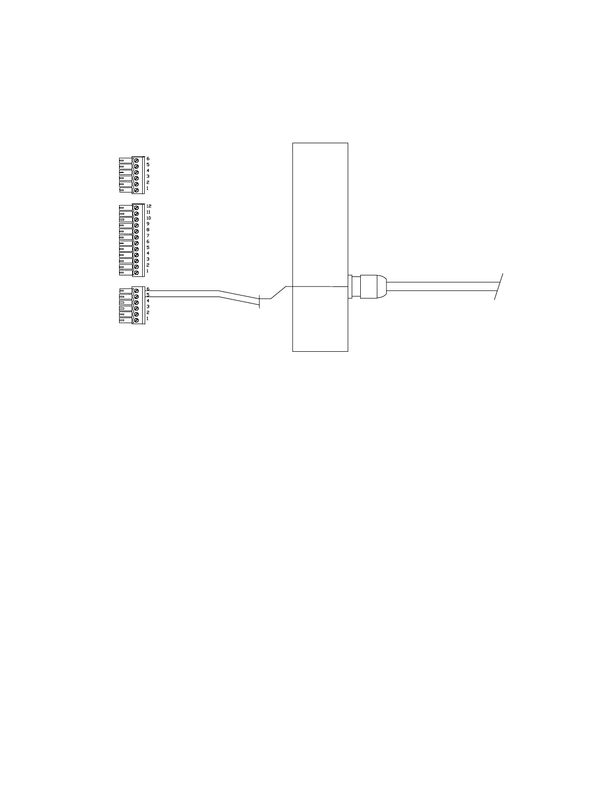
Connecting a Rudder Angle Indicator
SIGNAL
RETURN
Right-Side, Optional RAI Connection
The cable gland for a Rudder Angle Indicator is in your Accessory Kit.
We do not supply a cable for this installation.
We recommend #22 AWG, two conductor cable; it must be round, in order to make a
water-tight seal in the gland. The outer diameter of this cable must not exceed ¼”
(6.5 mm), nor be less than 5/32” (4 mm).
The gland for this output must be mounted on the right side end cap. To locate the hole
for the gland, look on the inside of the end cap. You will see several places where the
plastic has been formed so that a hole may be easily drilled.
Drill the hole using a 15/32” (12 mm) drill.
Place the gland from the Accessory Kit in the drilled hole. Fasten it into the end cap
with the supplied plastic nut, and tighten securely.
Feed the RAI cable though the gland, connect it as shown above, and then tighten
down the gland’s outer water-seal/strain-relief piece securely.
Document PN 29010012 V1.3
65