ComNav G3 GPS Compass Installation & Operation Appendices
Document PN 29010092 V2.3 - 32 -
Appendix 3 – G3 GPS IMO Installation
G3 GPS Compass system is an IMO compliant Heading Transmitting Device. As the
system is specifically designed to work in NMEA 0183 environment, specific
installation requirements for G3 must be followed to ensure the safety and to
maintain the IMO compliant status.
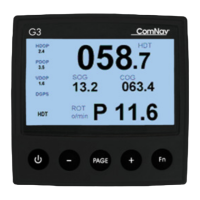
G3 Compass Display with G2/G2B
Accessories requirements
To install your G2 GPS with G3 in a NMEA 0183 environment, your G2 cable
must support G3 interface. Check that you have G2-CAN connection accessories
(Table 6) in your package.
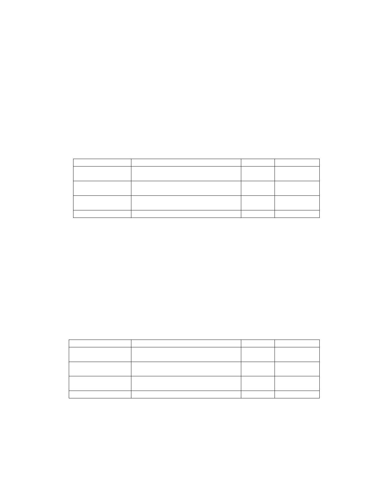
GNSS G2 IMO
cable
15 meter G2 cable 1
15m - 31110061
30m -31110062
CAN connection
cable
1 meter, female-connector-to-lead
cable
1 31110063
Terminator CAN bus termination connector with
120ohm termination resistor
1 3180016 or
3180015
T-Connector 1 31810008
Table 7 – IMO Installation Accessories
System Interconnections
A basic G3 GPS Compass has one G2 GPS and one G3 Display. The CAN
connection cable (PN 31110063) and G2 IMO Cable are provided with free leads,
allowing easy in-field installation. Typically you will have other NMEA 0183 devices
such as a navigator plotter or radar that will use the data from G2. All devices that will
receive data from G2 GPS can be connected through a junction box using standard
double row barrier strips. Figure 25 shows the block diagram of such a system. The
wiring diagram is given in Figure 26. Please note that the barrier strips must be
installed in a shielded metal water-protect box.
You must connect an audible device to the Alarm output to compliant with IMO
regulation.
Vector G2/G2B
IMO cable
15 meter G2 cable 1
15m - 31110058
CAN connection
cable
1 meter, female-connector-to-lead
cable
1 31110063
Terminator CAN bus termination connector with
120ohm termination resistor
1 31810016 or
31810015
T-Connector 1 31810008
Table 7 – Vector G2 IMO Installation Accessories