ComNav G3 GPS Compass Installation & Operation Tables & Figures
Document PN 29010092 V2.3 - 5 -
List of Figures
Figure 1 – Mounting template ........................................................................................................................................ 8
Figure 2 – Illustration of mounting process .................................................................................................................... 8
Figure 3 – G3 connection to NMEA 2000 GPS compass ............................................................................................... 9
Figure 4 – G3 connection to NMEA 0183 GPS compass ............................................................................................. 10
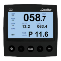
Figure 5 – G3 splash screen ........................................................................................................................................ 11
Figure 6 – G3 keypad layout ........................................................................................................................................ 13
Figure 7 – Example of keypad status bar ..................................................................................................................... 14
Figure 8 – Visual components of a data field on a screen page................................................................................... 14
Figure 9 - Alarm View Explanation ............................................................................................................................... 15
Figure 10 – Large Compass screen ............................................................................................................................. 16
Figure 11 – Small compass screen .............................................................................................................................. 16
Figure 12 – GPS satellite strength bar screen ............................................................................................................. 16
Figure 13 - Satellites in View screen ............................................................................................................................ 17
Figure 14 – Date and Time screen ............................................................................................................................... 17
Figure 15 – Rate of Turn screen .................................................................................................................................. 17
Figure 16 – Position screen ......................................................................................................................................... 18
Figure 17 – Digital layout with 3 fields .......................................................................................................................... 18
Figure 18 – G3 Menu tree ............................................................................................................................................ 19
Figure 19 - Virtual Keypad ........................................................................................................................................... 20
Figure 20 – Example of G3 night vision mode ............................................................................................................. 21
Figure 21 – Detect data sources through menu ........................................................................................................... 21
Figure 22 – Assign a device for a PGN ........................................................................................................................ 22
Figure 23 – Main menu when there is an alarm ........................................................................................................... 22
Figure 24 - Acknowledge an alert condition from Alarm menu ..................................................................................... 22
Figure 25 - Change PGN rates of an NMEA 2000 transducer ..................................................................................... 23
Figure 26 - Screens during setting PGN rates ............................................................................................................. 24
Figure 27 - IMO installation block diagram ................................................................................................................... 33
Figure 28 – G2 IMO wiring diagram ............................................................................................................................. 34
Figure 29 - G3 connection to NMEA 0183 Vector GPS compass ................................................................................ 35
Figure 30- Vector G2 IMO Wiring ................................................................................................................................. 36
List of Tables
Table 1 – Parts in the G3 Display Package.................................................................................................................... 7
Table 2 - Alert Conditions Reference ........................................................................................................................... 15
Table 3 – List of protocol and response-at-request PGNs ........................................................................................... 29
Table 4 – List of received PGNs .................................................................................................................................. 29
Table 5 – List of abbreviations for field name............................................................................................................... 30
Table 6 – List of abbreviations for units ....................................................................................................................... 31
Table 7 – IMO Installation Accessories ........................................................................................................................ 32
Table 8 – User Notes .................................................................................................................................................. 43