ComNav G3 GPS Compass Installation & Operation Appendices
Document PN 29010092 V2.3 - 33 -
System Interconnections
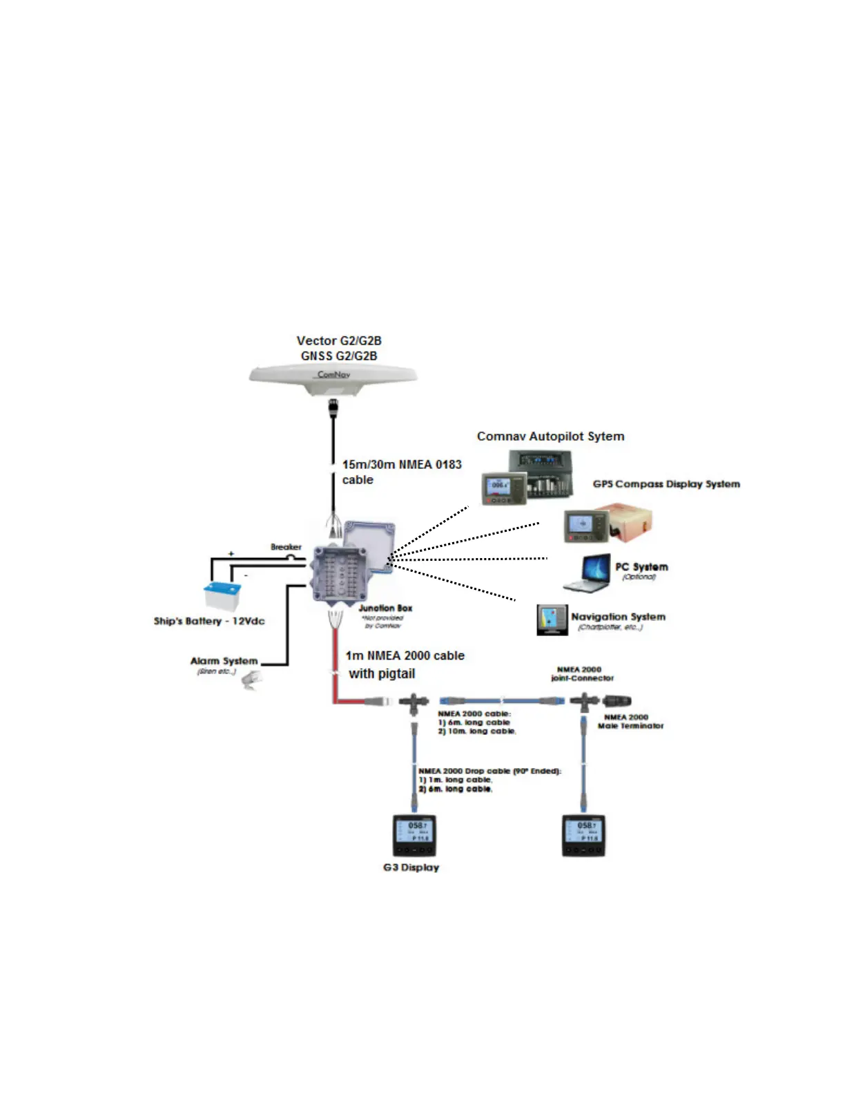
A basic G3 GPS Compass has one G2 GPS and one G3 Display. The CAN
connection cable (PN 31110058) and G2 IMO Cable are provided with free leads,
allowing easy in-field installation. Typically you will have other NMEA 0183 devices
such as a navigator plotter or radar that will use the data from G2. All devices that will
receive data from G2 GPS can be connected through a junction box using standard
double row barrier strips. Figure 25 shows the block diagram of such a system. The
wiring diagram is given in Figure 28. Please note that the barrier strips must be
installed in a shielded metal water-protect box.
Figure 27 - IMO installation block diagram