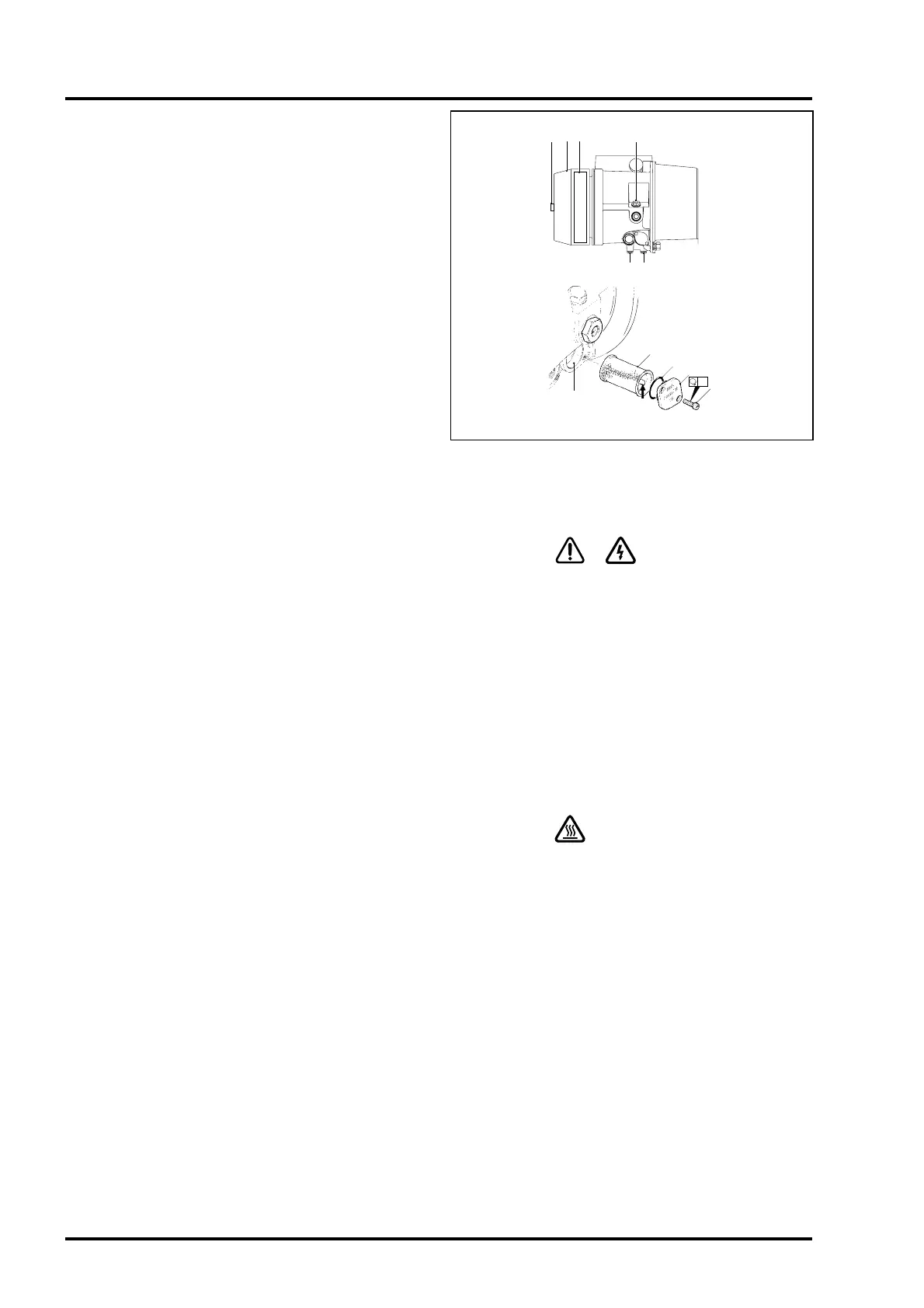
Oil draining procedure (Fig 1.3)
•
Wait until air-end vent down cycle is complete.
•
Open test valve to vent pressure from air aftercooler and
associated pipework.
•
Check that compressor air-end pressure gauge reads xero.
•
Carefully unscrew compressor filler plug (A).
•
Remove plug (A), discard bonded seal (B).
•
Place a shallow 5 litre container below the oil drain plugs (F).
•
Carefully remove drain plugs (F). Discard bonded seals (G).
•
Collect all oil drained from the compressor.
Oil filling procedure (Fig 1.3)
•
Fill to overflow with an approved oil (e.g. Fluid Force).
•
Refit filler plug (A) using a new bonded seal (B). Tighten to 25
Nm.
•
Check that air outlet and test valves are closed.
•
Ensure that all covers, guards and plugs are securely fitted.
•
Remove safety notices.
•
Start the compressor in manual mode and run for 30 seconds
only, then stop. Top up oil level as per oil level as per oil top up
procedure 8.4.
•
Reinstate all panels and covers.
• Test run the compressor and check pressure, temperature.
Inspect for oil leaks.
•
Ensure panels are fitted and secured, and that air outlet valve is
open before leaving.
Note: All discarded items and waste oil must be disposed of in an
approved manner.
Check drive shaft oil seal and drive end cover
bonded seals
The drive shaft oil seal is located in the drive end cover of the
compressor air-end. The clamping bolts securing the rotor stator
unit pass through the drive end cover and are sealed by bonded
seals. The drive end cover is located inside the bell housing and is
not directly visible.
•
Stop compressor and isolate from mains electrical supply.
•
Remove rubber blanking plug locaterd in the bell housing.
•
Using a flash light, check fo rtraces of oil around drive shaft oil
seal, bonded seals and inside bell housing.
•
If no oil is found, refit rubber blanking plug.
•
If oil is found, identify location of leak and renew seal.
Note: This is a major service task and should be carried out by
fully trained service engineers following procedures described in
separate Service Manual. If in doubt contact your Hydrovane
Distributors.
Electrical checks
WARNING !
•
Open the starter panel door.
•
Remove any terminal covers fitted to contactors and incoming
supply terminals.
• Check for any signs of overheating and ensure that all electrical
connections are tightened to correct torque settings, as per label
on inside face os starter.
Note: Pay special attention to power connections and cables
connected to contactors and incomming terminals.
•
Lock starter panel door and remove key to prevent unauthorised
access.
Clean and check electric motors
WARNING !
•
Remove any dust or dirt from motor bodies and motor air intake
grills.
•
Lubricate motor bearings as per manufacturers instructions.
•
Reinstate all covers.
•
Remove safety notices.
Page 20
CompAir Hydrovane Limited
1 Routine Servicing
C D E A,B
M
H
J
K
L
15
Nm
F, G F, G
Figure 1.3 - Filters and Drain Plug Location