Refer to Health and Safety section before carrying
out any service work.
Removing compressor drive coupling
•
Remove compressor from bell housing.
•
Secure drive coupling (6) using service tool (103). Remove
locknut (8) and washer (7).
•
Using an extractor tool remove coupling (6).
•
Remove retaining wire (4).
•
Remove oil seal (3).
•
Fit parts contained in service kit.
•
Fit new oil seal assembly using service tool (1302). Ensure oil
seal and shaft are dry. Wirelock in place. Refit washer and
locknut.
Note: If it is necessary to remove or disturb the motor coupling, it
must be accurately reset to the following procedure.
•
Measure distance (X).
•
Slide motor coupling (10) onto the motor shaft until the distance
measured between motor contact face and motor coupling face
equals dimension (X minus 2mm).
•
Lock coupling in position.
Oil Seal and Drive Arrangement
•
Remove compressor from motor (see page 2).
•
Remove coupling element (9). Examine for wear or damage.
Renew if necessary.
•
Unscrew drive locknut (8) and remove washer and compressor
coupling (6).
•
Renew oil seal assembly (3) and its ‘O’ring (2) taking care not to
damage the oil seal on the shaft keyway.
•
Apply Loctite 242 to rotor thread. Refit locknut (8) and tighten to
130 Nm.
IMPORTANT!
IF IT IS NECESSARY TO REMOVE OR DISTURB THE MOTOR
COUPLING, THEN, ON ASSEMBLY, IT MUST BE RESET
ACCURATELY FOLLOWING THE PROCEDURES BELOW TO
OBTAIN 1.5 mm CLEARANCE BETWEEN THE COMPRESSOR
AND MOTOR COUPLINGS.
•
Measure the distance between the compressor coupling face
and the bell housing contact face. This is dimension X.
•
Slide the motor coupling (10) onto the motor shaft until the
distance measured between the motor contact face (dimension
Y) and the motor coupling face equals dimension X minus
1.5 mm.
•
When the motor coupitng/impeller assembly is correctly
positioned on the motor shaft, apply Loctite 242 to grubscrews
(11)on the motor coupling and tightenitto the specified torque.
Page 46
CompAir Hydrovane
2J Drive Coupling Arrangement
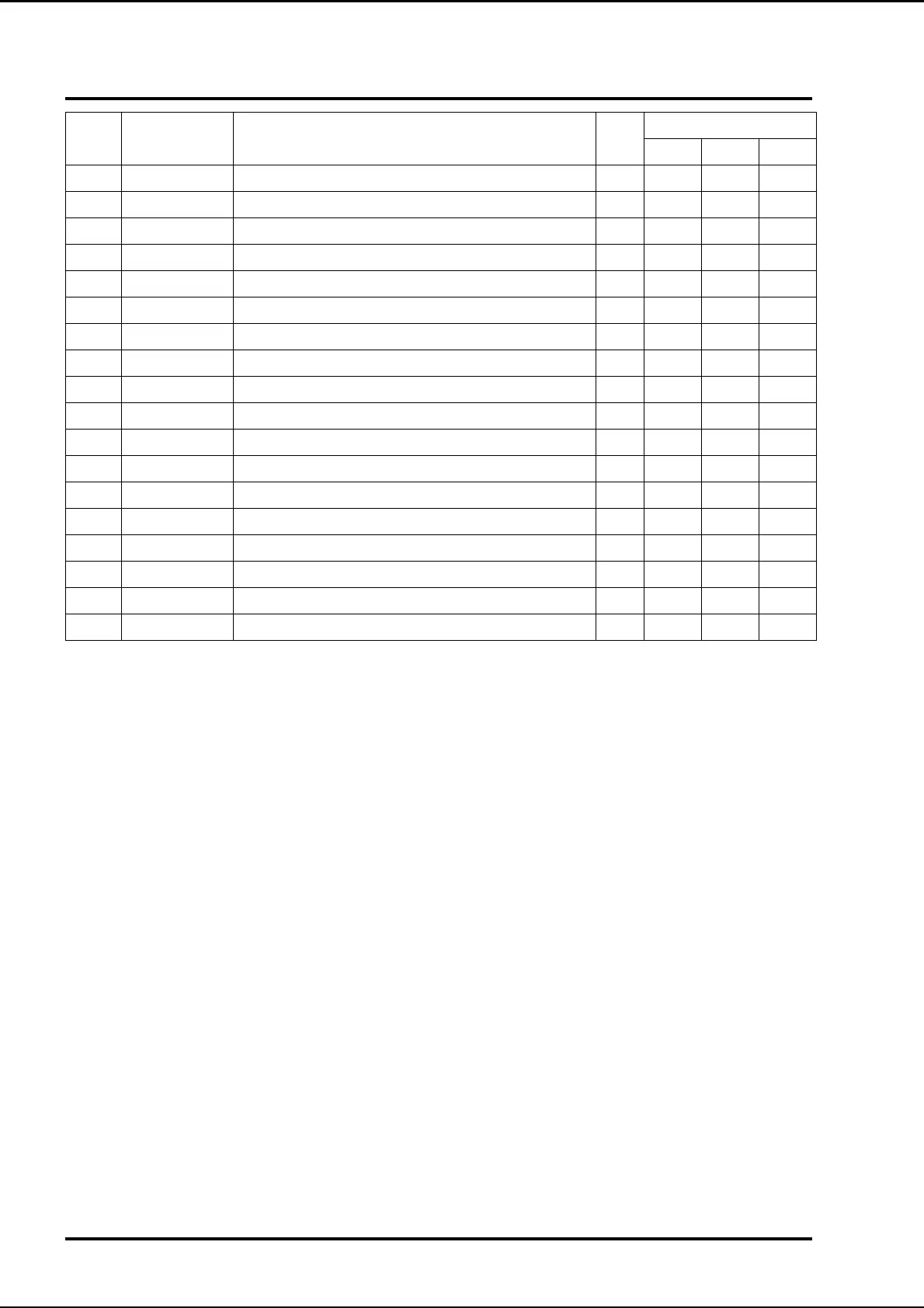
Item Part Number Description Kit
Quantity
All 705 707
1 57802 Key 94mm diameter 1
2 9810 ‘O’ Ring KT71 1
3 34222 Oil seal housing assembly (replacement) KT71 1
6a 72351 Drive coupling compressor (cooler plate) 1
6b 72350 Drive coupling compressor (panel cooler) 1
6c 73570 Drive coupling comp (toroidal cooler) 1
7 MW20 Washer M20 1
8 MN120 Lock nut M20 1
9a 71180 Coupling element (Toroidal cooler) KT71 1
9b 71890 Coupling element (panel cooler) KT71 1
10a 71179 Drive coupling motor (cooler plate) 1
10b 72349 Drive coupling motor (panel cooler) 1
10c 72320 Drive coupling motor (toroidal cooler) 1
71178 Coupling - complete
10d 71990 Coupling, Motor
11 MG710-16 Grub screw M10 x 16 2
12 ST213924 Loctite A/R