Refer to Health and Safety section before carrying
out any service work.
Minimum Pressure Valve
•
Disconnect vent-down pipe (15) and remove elbow (2).
•
Beforeremoving the valvebody (4), unscrew adjuster (3) to ease
spring pressure.
•
Removal of non-return valve (11) assembly is simplified using
long nosed pliers.
•
Examine valve seat (12) for damage. Renew if necessary.
•
Renew ‘O’ rings (5, 6 & 7). Silicon grease must be applied to
these ‘O’ rings prior to fitting them to the valve body.
•
On assembly, fit springs (9 & 10), piston (8) and the non-return
valve assembly (11, 12, 13 & 14) to the valve body, before
inserting the valve body into its housing.
•
To enable the valve body to be fully inserted, spring pressure
must be eased by fully unscrewing the adjuster (3).
•
After circlip (1) has been refitted to secure the assembly, screwin
adjuster (3) to an approximate depth of 12 mm.
Note: This is only a temporary setting.Further adjustment will be
required (see Section 3, TESTING) to obtain the correct minimum
pressure setting. Elbow (2) and vent-down pipe (15) need not be
fitted until testing is finished.
Page 40
CompAir Hydrovane
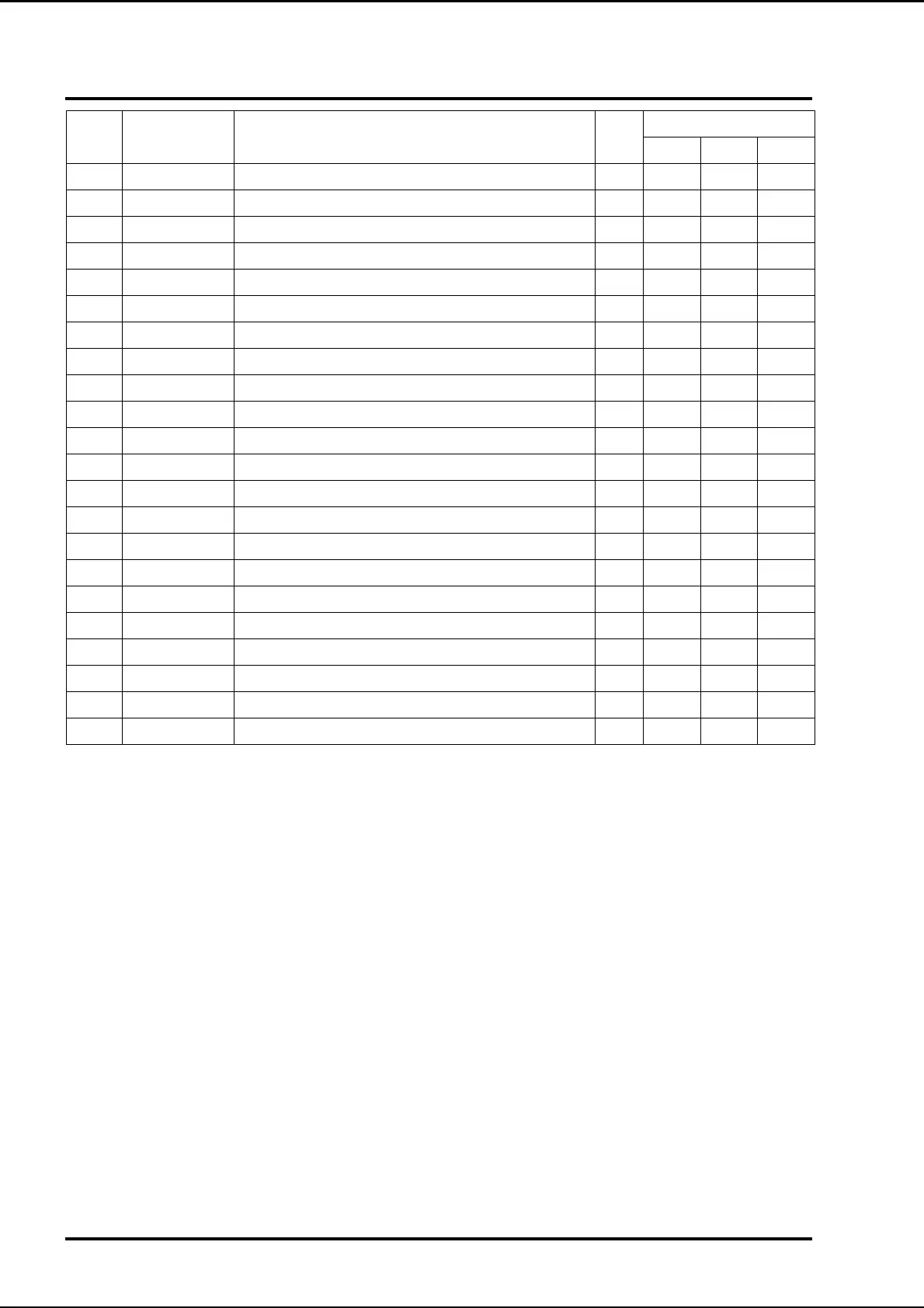
2G Minimum Pressure Valve and Oil Separator
Item Part Number Description Kit
Quantity
All 705 707
1 MCI-30 Circlip internal 1
33413 Minimum pressure valve assembly 1
2 50225 Male stud elbow 1/4 BSPT-6mm 1
3 58470 Adjuster plug 1
4 57742 M.P.V body 1
5 9758 O ring KM71 1
6 9717 O ring KM71 1
7 9711 O ring KM71 1
8 57842 M.P.V Piston 1
9 57588 Spring 1
10 57845 M.P.V Return spring 1
11 71760 Non return valve 1
12 0071 M.P.V Seat KM71 1
13 W3 Washer 3/16 1
14 MCE4-8 Circlip external 1
15 See Ventdown assemblies