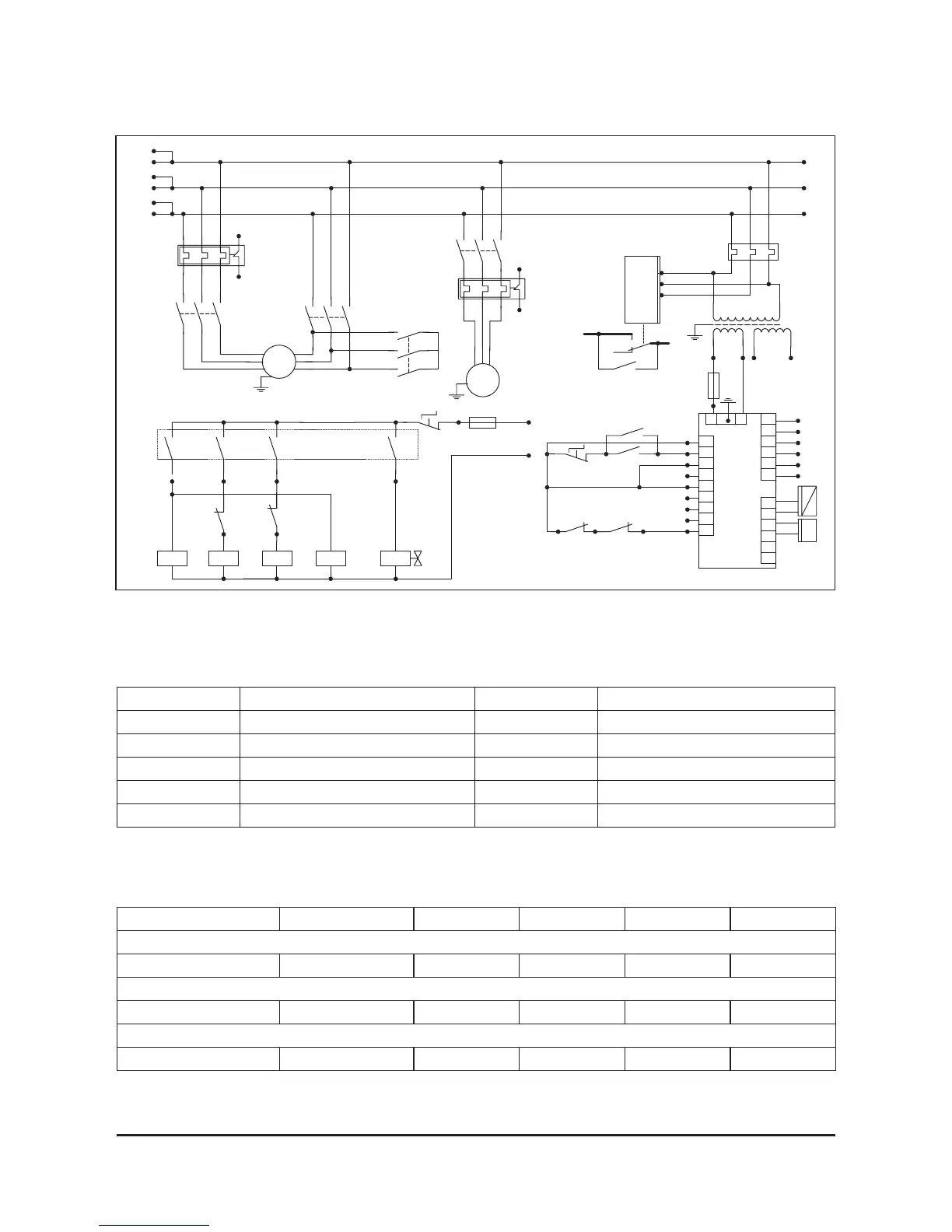
EasyManua.ls Logo

Comprag A55 - Electrical Diagram and Main Components; Electrical Connection Values

Default Icon
88 pages
Print Icon
To Next Page IconTo Next Page
To Previous Page IconTo Previous Page
Loading...
12
Version 4.5
Main components
К1, K2, К3, К4 Contactor YA Solenoid valve
М1, М2 Electric motor R Electronic controller
Т Temperature sensor I/P Pressure sensor
SB Emergency stop TN1, TN2 Overload relay
F1, F2 Fuses TR Transformer
PK1.1 Phase sequence relay QS Automatic power switch
2.7 General description
Voltage (V) Frequency (Hz) A30.. A37.. A45.. A55..
Мaterial - copper. Cable size (mm²)
380 / 400 50 16 25 35 50
Fuse value (A)
380 / 400 50 63 80 100 125
Motor overload relay (A)
380 / 400 50 31,8 38,1 46,2 56
A30-A55
3~
M1
M
M
K1.1
K2.1
K3.1
101 100
F1
2A
1
2
1
2
3
3 X 380VAC
1
2
3
4
5
SB1.2
24VAC
102
X01
3~
M2
TN2
K4.1
300
301
302
303
304
TN1
300
303
Tr1 380VAC
PK1
X04
7
8
9
6
1
2
3
4
203
204
205
207
5
6
203
209
PK1.1
X03
1
2
3
I
P
X05
T
4
5
6
TN2.1TN1.1
303 304
201
220VAC
200
1
11
2
22
3
33
QS
K1.2
YA
Re1
A1
A2
K3
A1
A2
K1
A1
A2
K2
Re3
K3.1
Re2
K2.1
208206
Re4
201202203
F2
2A
SB1.1
209207205204
200
A1
A2
K4
301
302
K1.2
R
Fig. 2.6
Electrical diagram
A30-55
2.6 Electrical diagram and main components

Table of Contents

Related product manuals