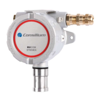
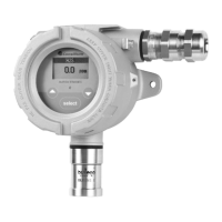
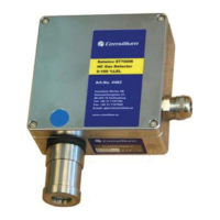
ST650EX / ST650-CO
2
/ ST350EX
v3.16
16
3.1 Functions
Output signal
Each ST650EX / ST650-CO
2
/ ST350EX sensing head is supplied with a transmitter PCB with a 4-
20mA interface. This transmitter PCB transforms the sensor signal to an analogue 4-20mA signal.
The sensing head has a number of predefined output levels.
Output signal Status
Sensing head is not connected
Power supply missing
< 2 mA System error / Sensor error
4-20mA Normal operation
> 22 mA Out of range / overload
Status-LED (main PCB)
The centre of the transmitter PCB features a status LED. This LED shows the current status of the
sensing head using a predefined flash sequence.
Colour LED flashes Description
GREEN
Continuous Normal operation
1 Calibration lock deactivated
2 Sensor not (correctly) connected
3 Sensor signal too low (ADC)
4 PID sensor signal too low
5 Signal < 2.4mA (-10% range)
RED
Continuous Overload >20mA
1 Signal not connected or electronic error
2 ADC error
3 Watch dog error
4 Error power supply sensor
5 Tx/Rx error IR sensor (black/purple connection wires)
RED/GREEN
Slow ASV routine active (Adjusting Sensor Voltage)
Fast ZERO / SPAN, minimum of maximum range