3. Hardware Description
PC-686BX(NLX)-LV, PC-686BX(NLX)-LVV
17
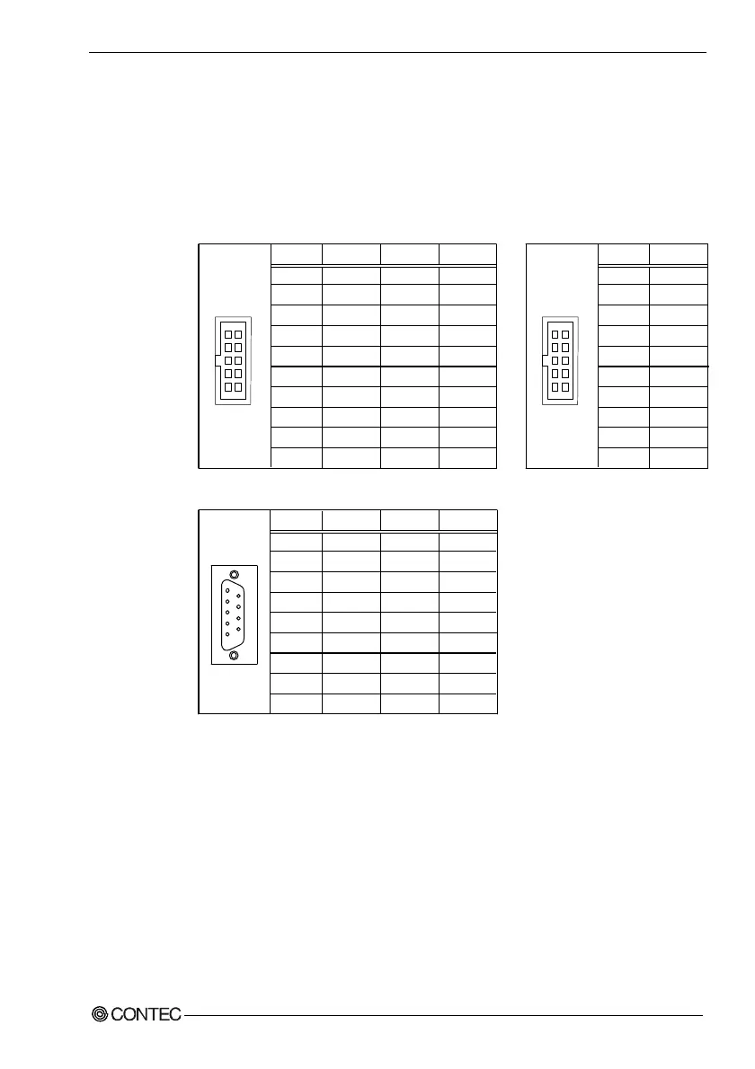
Serial Port Connector: CN2/CN3
COM1 (CN2) and COM2 (CN3) are on-board serial ports with 10-pin box head
connectors. The table below shows the pin layout for these connectors.
Table 3.4.
COM2(CN3) COM1(CN2)
Serial Port Connector
PIN
1
2
3
4
5
6
7
8
9
10
RS-232C
DCD
RXD
TXD
DTR
GND
DSR
RTS
CTS
RI
N.C.
RS-422
TX-
TX+
RX+
RX-
GND
RTS-
RTS+
CTS+
CTS-
N.C.
RS-485
TX-
TX+
RX+
RX-
GND
N.C.
N.C.
N.C.
N.C.
N.C.
CN3
1 6
5 10
PIN
1
2
3
4
5
6
7
8
9
10
RS-232C
DCD
RXD
TXD
DTR
GND
DSR
RTS
CTS
RI
N.C.
CN2
1 6
5 10
In case of using the accessory Cable (D-SUB 9pin)
PIN
1
2
3
4
5
6
7
8
9
RS-232C
DCD
RXD
TXD
DTR
GND
DSR
RTS
CTS
RI
RS-422
TX-
TX+
RX+
RX-
GND
RTS-
RTS+
CTS+
CTS-
RS-485
TX-
TX+
RX+
RX-
GND
N.C.
N.C.
N.C.
N.C.
1
5
9
6
Notes!
- For RS-485, TX+ (pin 2) and RX+ (pin 3) must be connected by a
jumper in the D-type connector.
- The same applies for TX- (pin 1) and RX- (pin 4).