3. Hardware Description
20
PC-686BX(NLX)-LV, PC-686BX(NLX)-LVV
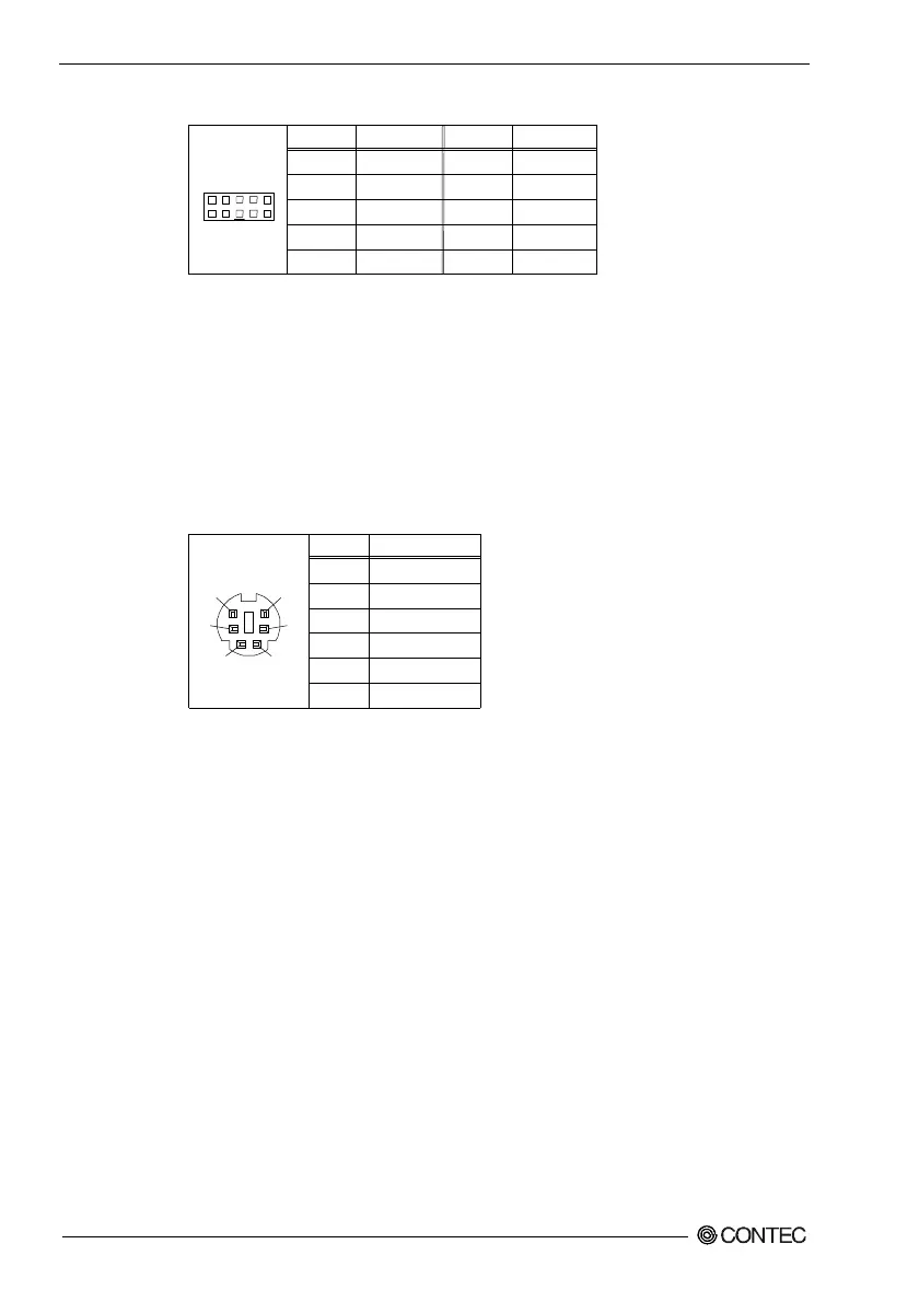
Table 3.5. CN4: USB Connector
Pin No.
1
3
5
7
9
Function
VCC
USBP0-
USBP0+
USBG
GND
Pin No.
2
4
6
8
10
Function
VCC
USB1-
USB1+
USBG
GND
CN4
1
2
9
10
Refer to "Chapter 8. Available Accessories" for a list of USB connector cables.
Keyboard Connector: CN11
The CPU board has a standard PS/2 keyboard MINI DIN connector for attaching the
keyboard. The keyboard can be plugged directly into this connector. The connector
pin layout is shown below.
Table 3.6. CN11: Keyboard Connector
Pin No.
1
2
3
4
5
6
Function
K.B DATA
N.C.
GND
+5V
K.B CLOCK
N.C.
3
6
4
2
1
5
CN11