4. Jumper Settings
PC-686BX(NLX)-LV, PC-686BX(NLX)-LVV
27
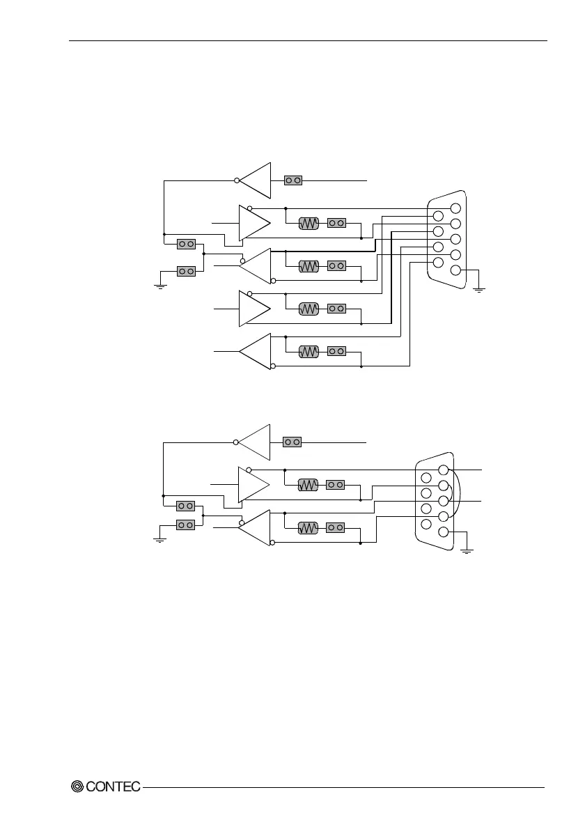
RS-422/RS-485 Receiver Disable Control Jumper Setting
The RTS signal is used for driver enable control when using the RS-422/RS-485 port.
Connecting pin 4 and pin 6 of JP2 disables the receiver and prevents the port from
receiving output data to external devices.
RTS#
JP2: 7-8
TXD#
TX-
RTS-
TX+
RTS+
RX+
CTS+
RX-
CTS-
JP3: 7-8
JP3: 5-6
JP3: 3-4
JP3: 1-2
D
R
D
R
RXD#
RTS
CTS
COM2
1
2
3
4
5
6
7
8
9
JP2: 5-6
JP2: 4-6
120Ω
120
Ω
120
Ω
120Ω
Figure 4.1. RS-422 Setup
RTS#
JP2: 7-8
TXD#
JP3: 7-8
JP3: 5-6
D
R
RXD#
COM2
1
2
3
4
5
6
7
8
9
JP2: 5-6
JP2: 4-6
120Ω
120
Ω
DATA-
DATA+
Figure 4.2. RS-485 Setup