4. Jumper Settings
26
PC-686BX(NLX)-LV, PC-686BX(NLX)-LVV
RS-232C/422/485 Selector Switch: JP1/JP2
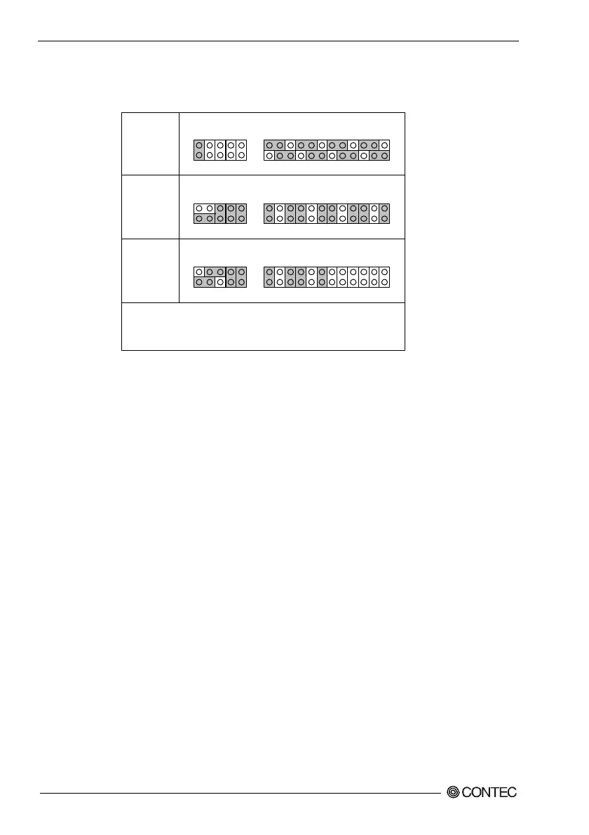
Table 4.2. JP1/JP2: RS-232C/422/485 Selector Switch
RS-232C
(Default)
RS-422
RS-485
1. For RS-485, the TX+ (pin 2) and RX+ (pin 3) lines must be
jumpered together in the D-type connector.
2. The same applies to the TX- (pin 1) and RX- (pin 4) lines.
JP2 JP1
2 4 6 8 10 2 4 6 8 10 12 14 16 18 20 22 24
1 3 5 7 9 1 3 5 7 9 11 13 15 17 19 21 23
JP2 JP1
2 4 6 8 10 2 4 6 8 10 12 14 16 18 20 22 24
1 3 5 7 9 1 3 5 7 9 11 13 15 17 19 21 23
JP2 JP1
2 4 6 8 10 2 4 6 8 10 12 14 16 18 20 22 24
1 3 5 7 9 1 3 5 7 9 11 13 15 17 19 21 23
Transmit Data Control for Half-Duplex Mode
The transmit buffer must be controlled to prevent transmit data collisions in half-
duplex mode. The port controls data transmission using the RTS signal and bit 1 of
the modem control register.
Modem Control Register
(I/O address + 4H) Bit 1: 0 ... RTS high (Transmit disabled)
1 ... RTS low (Transmit enabled)