A: Overview – Operator’s Panel
67
Power Control – Buttons and LED Patterns
The following table describes the panel’s LED light patterns and what they mean. The illustrations marked “startup – phase 1 (2,3,4)” show how the Operator’s
panel will look (LED lighting patterns) starting from when you turn the Main power switch ON, through the self-test procedures and until the scanner is ready to
scan.
NOTE: For simplicity, the illustrations below display a Standard Panel i.e., without an ATAC key. The LED behavior of the Power LED, Diagnostics LED and
Wait LED, are identical for Standard and ATAC operator’s panels
How it looks on scanner… What it means….
Turn the scanner power ON – First Time – Main Power ON
At back of the scanner, plug in the power cable and flip the main power switch to ON. The scanner starts the self-
test procedure which starts with the Init Sequence (see next).
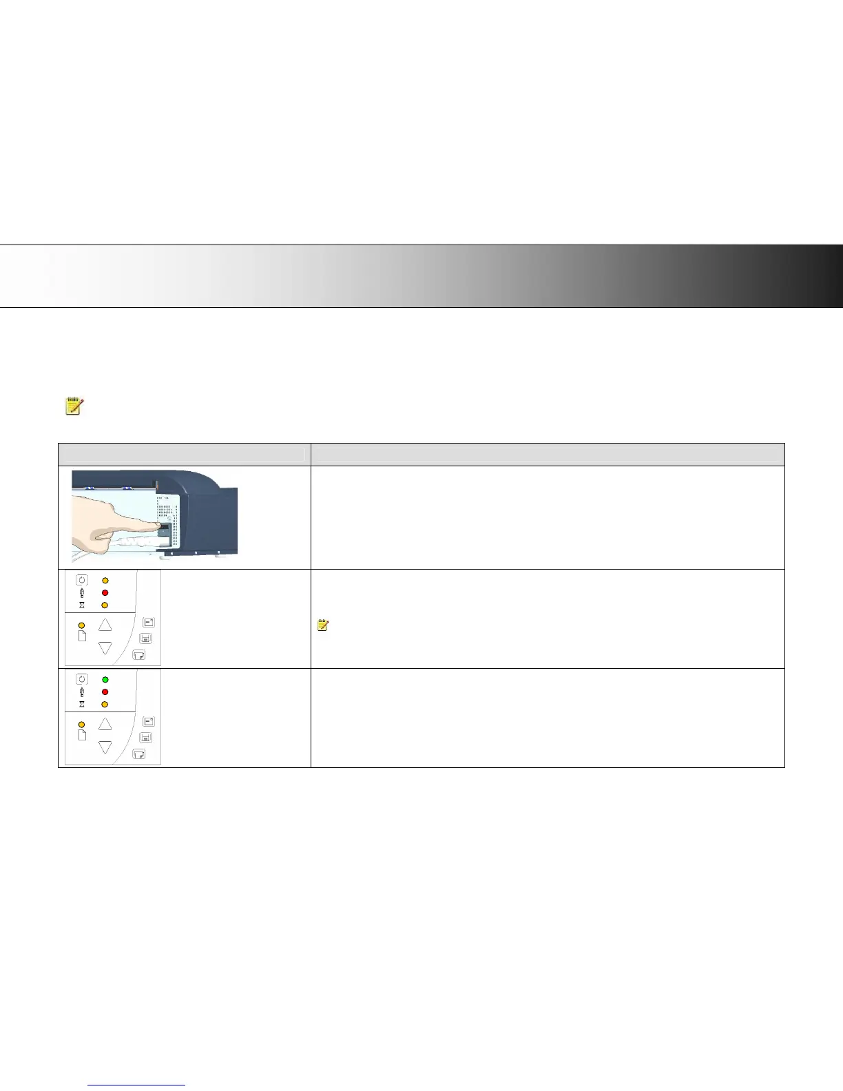
Init Sequence (startup phase 1)
When you turn main power On, the scanner runs it initialization sequence. ALL the LEDs are lighted as shown in the
illustration on the left.
At this point, panel input is disabled and you cannot begin scanning.
NOTE: When you power up through Wake-up, (by pressing the power key), this initialization sequence is skipped
and the scanner goes directly to Self-Adjustment (startup-phase 3).
Power LED Green (startup – phase 2)
Towards the end of Init Sequence, the Power LED will change to green while the other LEDs remain unchanged
(lighted).
From here the scanner moves on to Self Adjustment (startup phase 3).
 Loading...