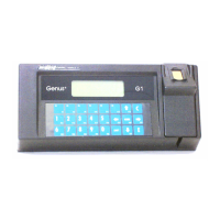
Genus G1 MARK II Users Manual
UM3010-2
Data Input/Output (Optional)
The data input/output port provides three digital
inputs and a Wiegand data port. The Wiegand
Data port provides Data0/Data1 input or output
signals. If connected to a reader will accept the
Wiegand data or can transmit Wiegand data to an
external device. A pluggable connector is
supplied with the terminal.
Connector: 8 position Terminal Block
Pinouts:
1 = + 5VDC 5 = DI 3
2 = Ground 6 = +18 VDC
3 = DI 1 7 = Wiegand Data 0
4 = DI 2 8 = Wiegand Data 1
Relay (Optional)
The Relay output configuration supports both
sourcing and non-sourcing. The relay is a Form
C contact relay rated for 1 amp @ 30V AC/DC.
The relay can be used for external low voltage
devices such as control or for monitoring doors,
bells, and alarms.
Connector: 5 position Terminal Block
Pinouts:
1 = Normally Open (N.O.)
2 = Common (C)
3 = Normally Closed (N.C.)
4 = Ground
5 = +18 VDC
Standard Power Port
Power is supplied to the Terminal via a standard
Barrel Jack on the backplate of the Terminal.
Connector: Barrel Jack (2.5mm)
Pinouts:
1 = +15V to 20VDC
2 = Power Ground
Peripheral Power Port
Power is supplied from the Terminal to CMI
peripherals plugged into the Peripheral Power
Port on the backplate of the Terminal.
Connector: 8 position
Pinouts:
1 = +18 VDC 5 = +Vnet
2 = +5 VDC 6 = -Vnet
3 = +3.3 VDC 7 = Wiegand Data 0
4 = GND 8 = Wiegand Data 1
Revision B 10-30-07 10