Genus G1 MARK II Users Manual
UM3010-2
Terminal Connections
Terminal connections apply to both Genus G1 and G1 Hardened Terminals.
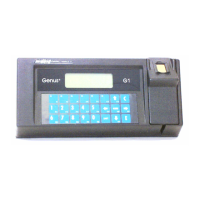
Terminal Back
NOTE: All available options are shown, some models may differ.
The Ethernet port supports the 10/100BASE-T
network connections. The Ethernet port is
located on the backplate of the Terminal and
connects directly to CAT-5 cable.
Note: Power is not available from the Ethernet
port without the jumpered connector on the
Peripheral Power Port.
Connector: 8 position RJ45.
Pinouts:
1 = Receive + 5 = +Vnet
2 = Receive – 6 = Transmit –
3 = Transmit + 7 = -Vnet
4 = +Vnet 8 = -Vnet
The Serial Aux port provides a serial connection
to interface to serial peripheral devices or for
modem communications.
Connector: 8 position RJ45.
Pinouts:
1 = DCD 5 = GND
2 = RXD 6 = +18 VDC (opt.DSR)
3 = TXD 7 = RTS
4 = DTR 8 = CTS
Wand / Scanner Port
The wand port provides CMI standard pinouts
with the RJ11 connector.
Connector: 6 position RJ11
Pinouts:
1 = Wiegand Data 0 4 = Wiegand Data 1
2 = Ground 5 = Data
3 = +5 VDC 6 = +18 VDC
Revision B 10-30-07 9