ALSPA PROFIBUS Field Bus Coupler 3. Installation
(09/06) Technical Manual Page 3-9
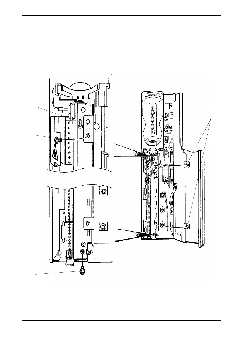
3. Release the screw (A) securing the plastic terminal shroud.
Remove and retain the two screws and washers (B) securing the
control module to the drive chassis.
Figure 3-6 Drive module – access and release the control board
C
B
B
A