Form 6 Microprocessor-Based Pole-mount Recloser Control Installation and Operation Instructions
24
1
65
43
2
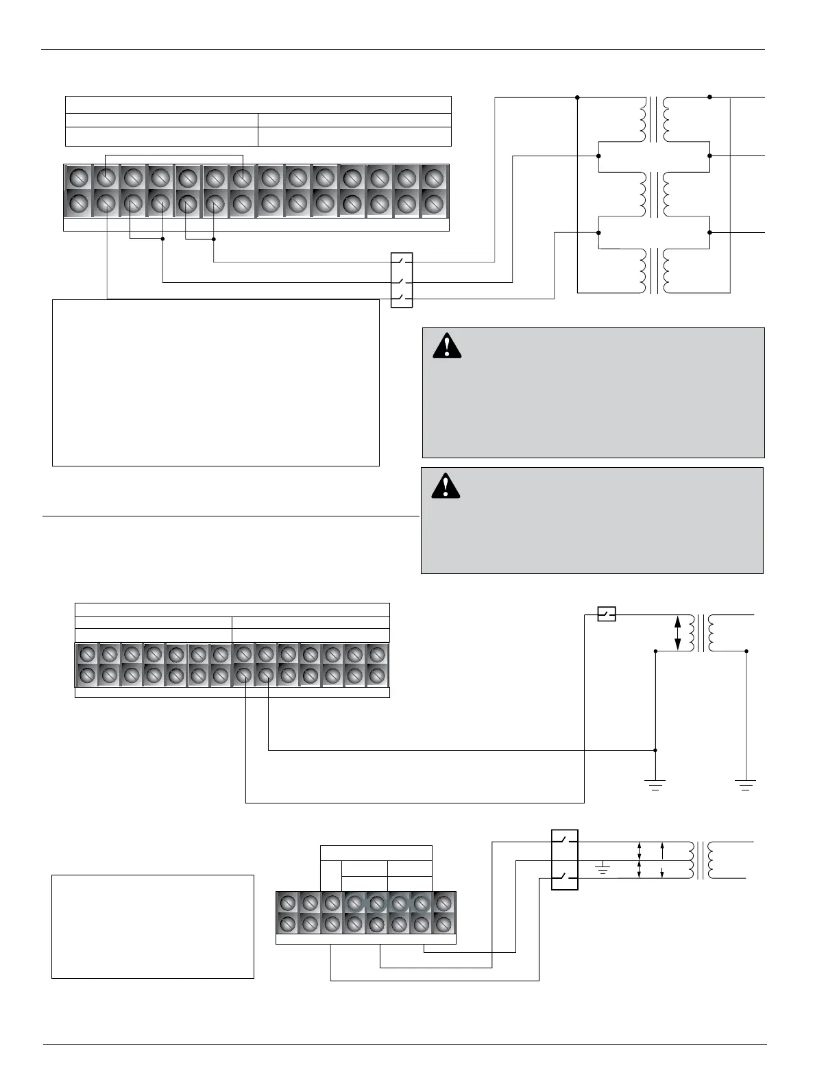
Power Connections
TB7
120/240
NEU
NEU
120 (L1)
240
120
120
BØ
1
4
3
2
7
1211
109
8
TB8
Voltage Sensing Connections
Source
Load
V (1-2) V(3-4)
V(5-6)
V1
V2
V3
56
120
Load Side
Source Side
NEU
YØ
User-Supplied
Disconnect
Switch
User-Supplied
Disconnect
Switches
120
(L2)
Figure 19.
240 Volt, 3-wire transformer connection. B phase input for Power and Sensing. *YØ for Sync Check Voltage.
Note: Terminal Block positions
TB7-3 and TB7-4 are
factory-jumpered together.
Terminal Block positions
TB7-5 and TB7-6 are
factory-jumpered together.
1
4
32
7
1211
109
8
TB8
Voltage Sensing Connections
Source
Load
V (1-2) V(3-4)
V(5-6)
V1
V2
V3
65
CØ
BØ
AØ
User-Supplied
Disconnect
Switches
Figure 18.
Customer connections to TB8, 120 VAC Delta Connection.
Note: Terminal Block positions TB8-1 and TB8-6 are
factory-jumpered together for Delta connection
only.
Terminal Block positions TB8-2 and TB8-3 are
factory-jumpered together for Delta connection
only.
Terminal Block positions TB8-4 and TB8-5 are
factory-jumpered together for Delta connection
only.
Remove factory jumpers for Wye application.
WARNING: Hazardous voltage. Before applying
power to the control, confirm that male pins of
the input power receptacle are electrically insulated to
prevent unintentional contact with 120V AC voltage.
Failure to do so may result in severe personal injury or
death. T372.0
DANGER: Hazardous voltage. Do not connect
potential transformer low-voltage secondaries to
the control through cables or other wiring until the unit is
installed in the field. Transformer high-voltage primary
windings will become live when 120V AC is applied to
the control from an alternate source if the transformer
secondary is connected. Failure to comply may result in
severe personal injury or death. T371.1
 Loading...