Form 6 Microprocessor-Based Pole Mount Recloser Control Installation and Operation Instructions
40
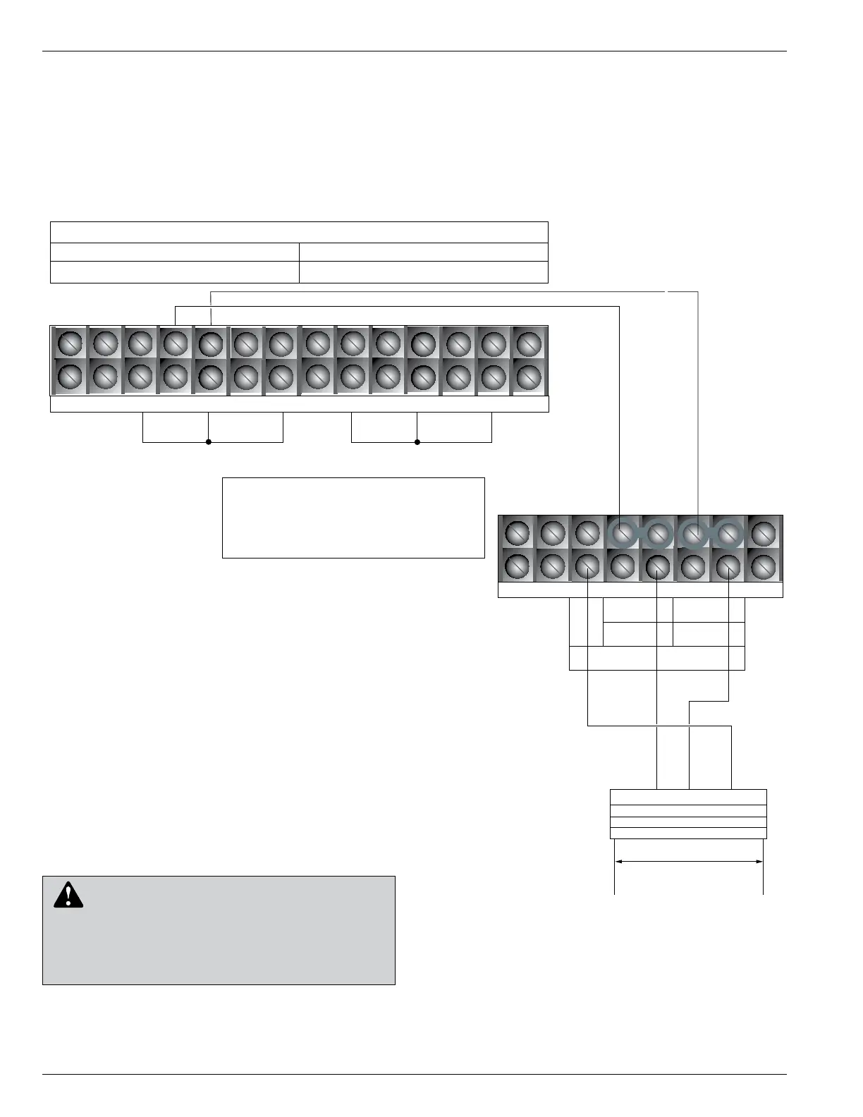
Note: Terminal Block positions TB7-3 and
TB7-4 are factory-jumpered together.
Terminal Block positions TB7-5 and
TB7-6 are factory-jumpered together.
WARNING: Hazardous voltage. Before applying
power to the control, confirm that male pins of
the input power receptacle are electrically insulated to
prevent unintentional contact with 120V AC voltage.
Failure to do so may result in severe personal injury or
death. T372.0
Figure 34.
240 VAC input receptacle, 3-pin (KME6-1775-K).
1
65
43
2
Power Connections
TB7
120/240
NEU
NEU
120 (L1)
1
4
3
2
7
1211
109
8
TB8
Voltage Sensing Connections
Source
Load
V (1-2) V(3-4)
V(5-6)
V1
V2
V3
5 6
BØ
White
120
(L2)
Factory Wiring for Wye Connection
Black
R2
A B C
3-wire 240 VAC
Incoming Power
Black
Red
Input
Receptacle
White
 Loading...