Installation/removal
Cornelius Deutschland GmbH
Document no. TD0003100
Version 18/03/2019, Index 0
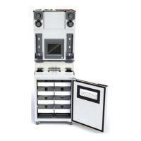
Installation and service manual Tower
Nueva
13
5.5 Still water option
For units with built-in soda dispensers, there is an option of converting the soda dispensers to still water in order to dispense non-
carbonated beverages at individual dispensing valves.
The procedure is described here using the connection of a soda dispenser as an example.
NOTICE!
• For units with 5 or 6 dispensing valves, the still water option is only available on the last three dispensing
valves on the right.
• For units with 8 dispensing valves, the still water option is only available on the last four dispensing valves
on the right.
Prerequisites References
The hood has been removed. see chapter 7.6
The dispensing valve to be assigned the still water option has
been removed.
See dispensing valve documentation
Spare parts ID/reference Qty/
amount
Comment
Locking screw 220094713 a. n.
1
Nozzle 149837500 a. n. Metric connections
Nozzle 318971000 a. n. Inch-based connections
Tubing clamp 440000306 a. n.
Seal for locking screw 317015000 a. n. 6.07 x 1.78
1. a. n. = as needed
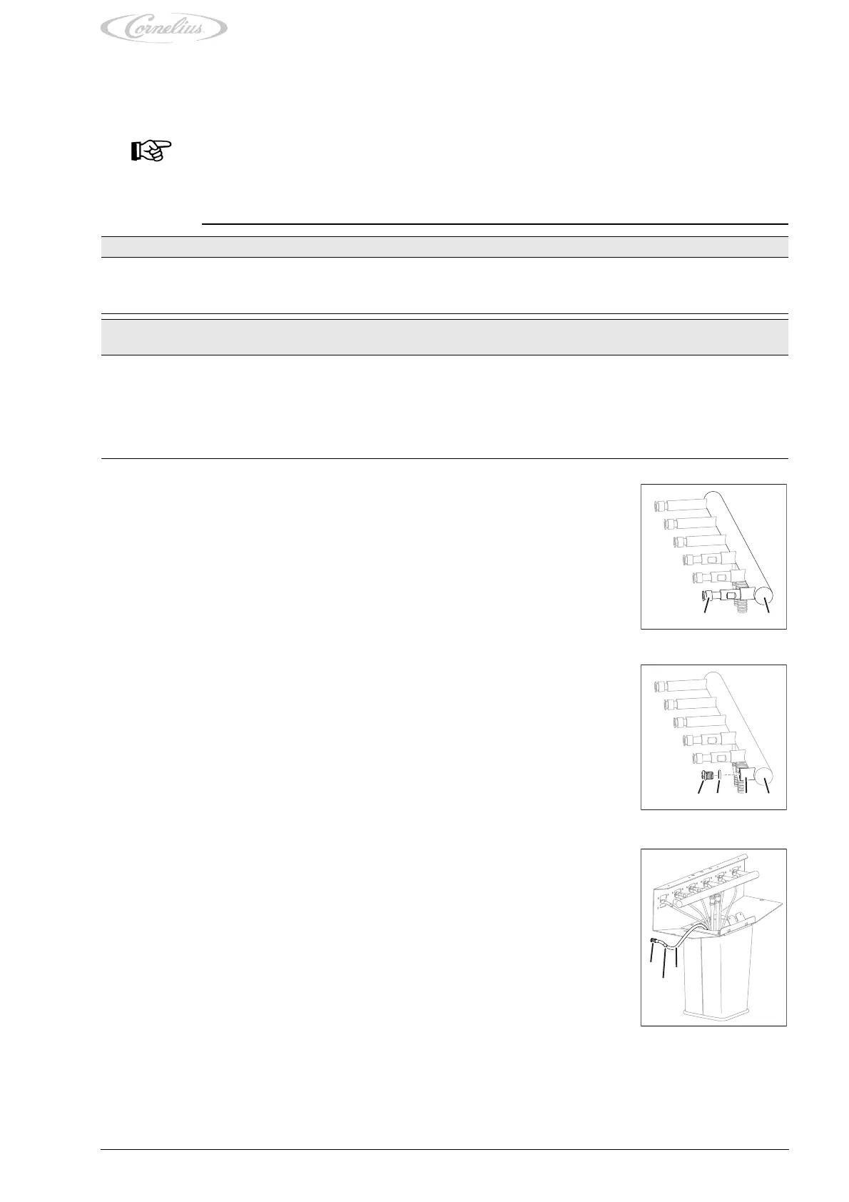
1. Remove the connection (Fig. 16/1) from the soda dispenser (Fig. 16/2).
Fig. 16
1
2
2. Place the seal (Fig. 17/3) over the locking screw (Fig. 17/4) and close the connection (Fig. 17/
2) of the soda dispenser (Fig. 17/1) using the locking screw (Fig. 17/4).
Fig. 17
24 3
1
3. If available, attach to an unused tube (Fig. 18/3) of the python a nozzle (Fig. 18/1) and attach
the tube (Fig. 18/3) using a clamp (Fig. 18/2) to the nozzle (Fig. 18/1).
Otherwise, install a new tube (Fig. 18/3) in the python.
4. Position the still water tube within the dispensing valve support.
5. Insulate the soda dispenser and the still water tube.
6. If applicable, connect the still water tube to the undercounter cooler; see the document “Un-
dercounter cooler installation and service manual”.
Finishing tasks
1. Install the hood; see chapter 7.6.
2. Mount the dispensing valve; see the dispensing valve documentation.
Fig. 18
3
2
1