START-UP
- 28 -
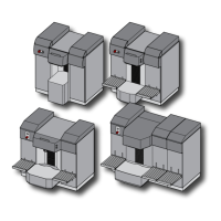
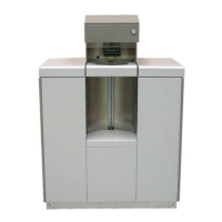
COROB™ D600 - D700 - D800TX
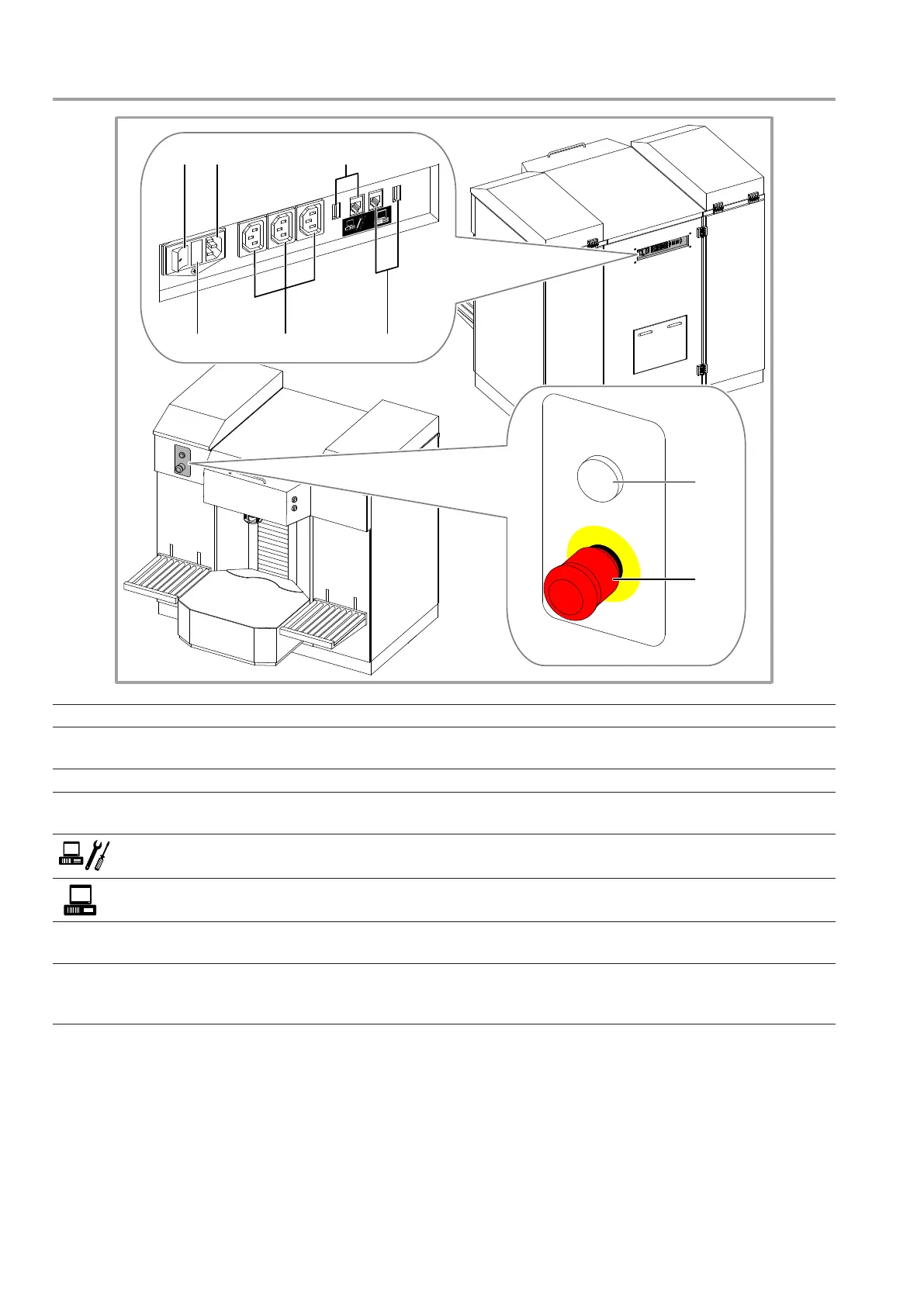
5.2 Control devices and connections
1. Machine main switch.
2. Fuse compartment.
The value of fuses is shown in the technical specications
table (chapter 8.1).
3. Main plug.
4. Auxiliary sockets.
Power supply to the computer and other equipment (calibration
scale or label printer).
5. Ports for service computer. USB or RS232 connection to the service computer.
6. Ports for management computer.
USB or RS232 connection to the machine management
computer.
7. ON lamp.
When this lamp is lit, it indicates that the machine is powered
and the main switch is in the ON position (I).
8. Emergency button.
Red mushroom-head button. This is the emergency stop
button for the machine, to use in case of a breakdown or
dangerous conditions (chapter 5.5).
0
1 3
2 4 6
5
7
8