● Lower switch 0 (SW0) - 5, 7, 17, and 19
IMPORTANT: Switch port assignments in the configuration diagrams are provided for reference only. For
system-specific inter-rack switch cabling, refer to the system-specific storage configuration document
(SCD).
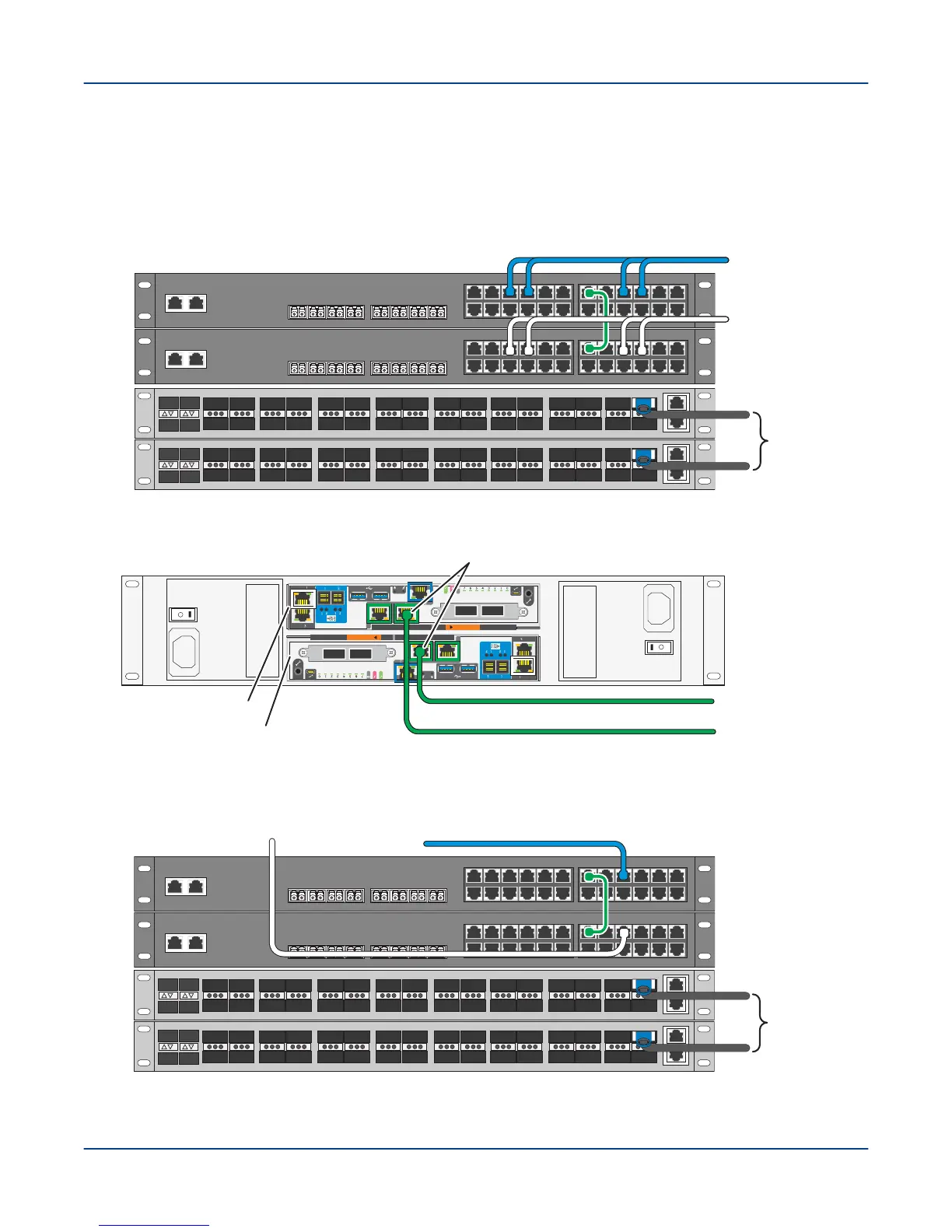
Figure 26. Cable Base Rack 36-Port 40GbE LDN and Dual 24-Port LMN Using Core Switch
LDN to
customer
core switch
40G1
40G0
1 2 3
4
5
6 7 8 9
10 11
12
13 14 15
16
17
18 19 20 21
22 23
24
X1 X2 X3 X4 X5 X6 X7 X8
1 2 3
4
5
6 7 8 9
10 11
12
13 14 15
16
17
18 19 20 21
22 23
24
X1 X2 X3 X4 X5 X6 X7 X8
SW1
SW0
LMN to storage
racks 1, 2, 3 ... N
SW1 switch
LMN to storage
racks 1, 2, 3 ... N
SW0 switch
Figure 27. Cable SMU to External Administration Network
A
B
To external
administration
network (EAN)
EAC A Node n000
EAC B Node n001
pub0 interfaces (NIC 5)
SMU
Figure 28. Cable Storage Rack 36-port 40GbE LDN and Dual 24-port LMN Using Core Switch
LDN to
customer
core switch
40G1
40G0
1 2 3
4
5
6 7 8 9
10 11
12
13 14 15
16
17
18 19 20 21
22 23
24
X1 X2 X3 X4 X5 X6 X7 X8
1 2 3
4
5
6 7 8 9
10 11
12
13 14 15
16
17
18 19 20 21
22 23
24
X1 X2 X3 X4 X5 X6 X7 X8
SW1
SW0
From base rack
SW1 switch
From base rack
SW0 switch
Environment Connections
42