The rack will require a total of four wiring looms as viewed from the rear: two for the left-hand side, and two for the
right-hand side. The colors of red and yellow have been selected as these are bright and colorful but also of
sufficient contrast to aid the color blind when servicing the rack.
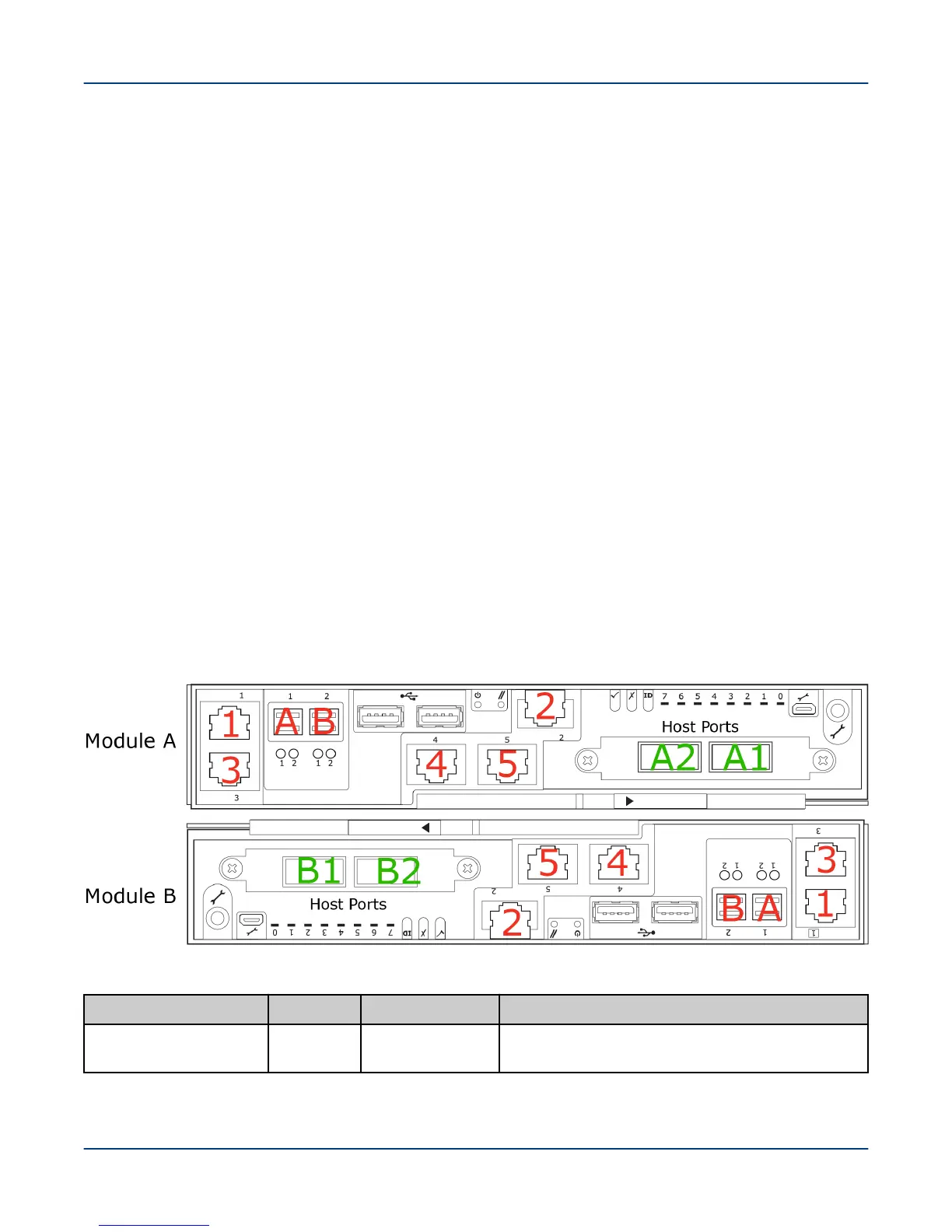
When components are located side by side, they will be identified as A for the left side and the B for the right side,
as seen when facing the rear of the rack. For example, SSU0-A is the lowest SSU left side EAC data network
connection, and SSU0-B is the lowest SSU right side EAC data network connection. Ethernet connections from
the EAC to the Ethernet switch have two possible connections for each side: A1 and A2, or B1 and B2. There are
3 to 5 Ethernet ports on an EAC depending on the type: 1 is on the right, and 2 is on the left.
Because Module B is inverted in the SMU and MMU, the cable colors will be consistent with the port to which they
connect The result of this inversion is that for this lower module (only), the port on the left has a red cable and the
port on the right has a yellow cable.
SMU and MMU node references shown in the network interconnect lists are numbered using physical node
numbers (same as the front control panel). See ClusterStor L300 and L300N SMU Physical and Logical Port
Numbering on page 99 and ClusterStor L300 and L300N MMU Physical and Logical Port Numbering on page
100 for more information.
Each cable is labeled at both ends to ensure correct routing with the label number. as provided in the network
interconnect lists, which provide the port connection information for each numbered cable.
All racks have a link between the two Ethernet switches that is shown as a green connection in the diagrams. This
link goes between port 13 (or 37 on a 48-port switch) on each switch regardless of the rack type.
Power Distribution Units (PDUs) are identified as PDU0 for the left side and PDU1 for the right side.
16.3.1 ClusterStor L300 and L300N SMU Physical and Logical Port Numbering
ClusterStor L300 and L300N SMU physical and logical port numbering.
Figure 69. SMU Physical and Logical Port Numbering
Table 7. SMU Physical and Logical Port Numbering
Physcial Port Label Logical Port Connection
Onboard NIC 1 1
meth0
Primary local management network (LMN) SW0
port for management and IPMI
Reference
99