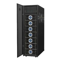
Figure 42. Base Rack with 32-Port 100GbE LDN and 24-Port LMN Using Core Switch
100G1
100G0
LDN to
customer
core switch
1 2 3
4
5
6 7 8 9
10 11
12
13 14 15
16
17
18 19 20 21
22 23
24
X1 X2 X3 X4 X5 X6 X7 X8
1 2 3
4
5
6 7 8 9
10 11
12
13 14 15
16
17
18 19 20 21
22 23
24
X1 X2 X3 X4 X5 X6 X7 X8
SW1
SW0
LMN to storage
racks 1, 2, 3 ... N
SW1 switch
LMN to storage
racks 1, 2, 3 ... N
SW0 switch
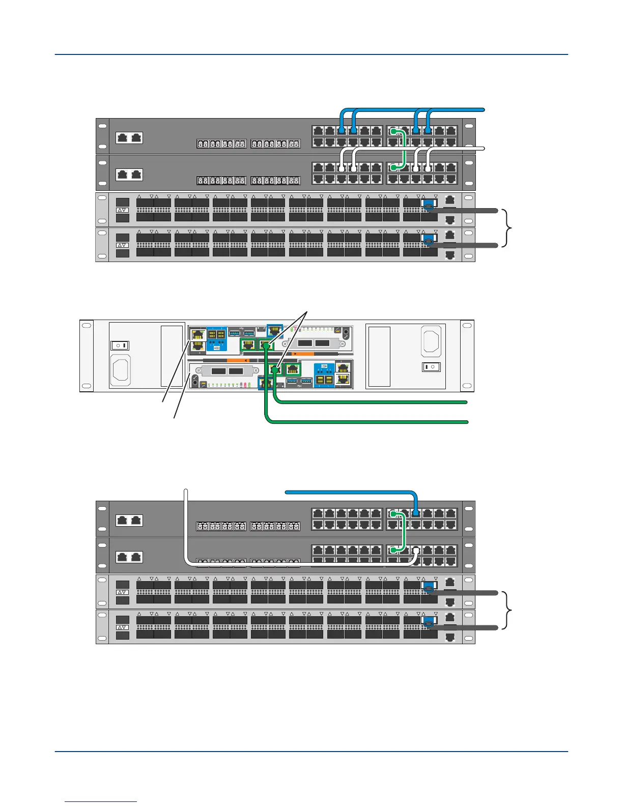
Figure 43. Cable SMU to External Administration Network
A
B
To external
administration
network (EAN)
EAC A Node n000
EAC B Node n001
pub0 interfaces (NIC 5)
SMU
Figure 44. Cable Storage Rack with 32-Port 100G and 24-Port LAN Using Core Switch
100G1
100G0
LDN to
customer
core switch
1 2 3
4
5
6 7 8 9
10 11
12
13 14 15
16
17
18 19 20 21
22 23
24
X1 X2 X3 X4 X5 X6 X7 X8
1 2 3
4
5
6 7 8 9
10 11
12
13 14 15
16
17
18 19 20 21
22 23
24
X1 X2 X3 X4 X5 X6 X7 X8
SW1
SW0
From base rack
SW1 switch
From base rack
SW0 switch
Procedure
1. In the base rack and each storage rack, connect a QSFP+ passive copper data cable to the lower 100GbE
switch (100G0 in the diagrams) (available ports listed above), and then to the customer core switch.
Environment Connections
53