20
The CS2325 Plug-on Adapter (continued)
Operation
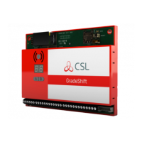
1. When first powered, the DualCom will detect the Plug-on Adapter and there-
after will always remember that it must be connected. The Operation LED
on the Plug-on Adapter will flash continuously when connection to the
DualCom is established.
2. When the Plug-on Adapter is connected then the 8 input terminals on the
DualCom are inactive. All inputs are provided by the plug-on pins.
3. Power for the DualCom and the Plug-on Adapter is provided by the Control
Panel via the plug-on pins.
4. Where ‘PD6662, BSIA 175’ fault operation is required between the DualCom
and the Control Panel, select this using the A&B buttons. Refer to Fault &
Aux Outputs on page 28 - 30 and Appendix 1, Tables 30, 31 and 32.
5. Where other fault operation is required between the DualCom and the Con-
trol Panel, make connections from the DualCom’s Fault and Aux relay out-
puts to suitable Control Panel inputs. Select the required operation using
the A&B buttons. Refer to the Fault & Aux Outputs on pages 28 - 30 and
Appendix 1, Tables 30, 31 and 32.
Returning DualCom to the ‘Stand-Alone’ mode
Where a DualCom has been used with a Plug-on Adapter and the DualCom is
now required in the ‘stand-alone’ mode (i.e. the Plug-on Adapter is no longer
required) then the DualCom’s Plug-on Adapter memory must be reset.
To reset the memory,
a). Unplug the Plug-on Adapter from the Control Panel and from the
DualCom.
b). Where fitted, unplug the CS2351 or CS2355 Expander Card.
c). Press and hold the A button.
d). With the A button still held, connect the supply (9-30 volts) to the
DualCom’s supply Terminals until the sounder ‘beeps’.

 Loading...